Toyota Venza: Installation
INSTALLATION
PROCEDURE
1. INSTALL POWER STEERING ECU ASSEMBLY
|
(a) Engage the 4 wire harness clamps to the power steering ECU assembly. |
|
.png)
|
(b) Install the power steering ECU assembly with the 3 nuts. Torque: 14 N·m {138 kgf·cm, 10 ft·lbf} |
|
.png)
|
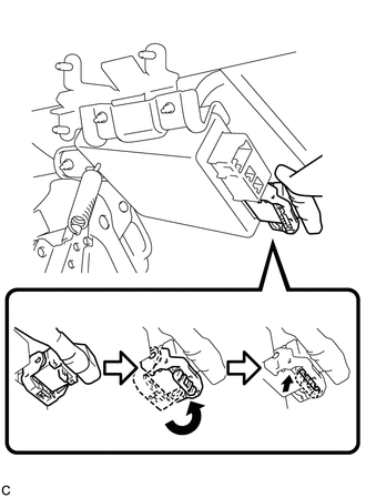
(c) Securely connect the connector to the power steering ECU assembly. HINT: Return the lock lever to its original position to connect the connector, and then securely push in the lock of the lock lever as shown in the illustration . |
|
|
(d) Connect the 3 connectors to the power steering ECU assembly. |
|
.png)
2. INSTALL DRIVER SIDE JUNCTION BLOCK ASSEMBLY
|
(a) Engage the 2 claws to install the driver side junction block assembly. |
|
.png)
(b) Connect the connectors to the back of the driver side junction block assembly.
|
(c) Install the driver side junction block assembly with the 3 nuts. Torque: 8.0 N·m {82 kgf·cm, 71 in·lbf} |
|
.png)
(d) Connect the connectors to the driver side junction block assembly.
3. INSTALL DRIVER SIDE KNEE AIRBAG ASSEMBLY
HINT:
Refer to the instructions for Installation of the knee airbag assembly (See page
.gif) ).
).
4. CONNECT CABLE TO NEGATIVE BATTERY TERMINAL
NOTICE:
When disconnecting the cable, some systems need to be initialized after the cable
is reconnected (See page ).
5. INITIALIZE ROTATION ANGLE SENSOR AND CALIBRATE TORQUE SENSOR ZERO POINT
(a) If replacing the power steering ECU assembly, clear the rotation angle sensor
calibration value, initialize the rotation angle sensor, and calibrate the torque
sensor zero point (See page ).
 Removal
REMOVAL
CAUTION / NOTICE / HINT
CAUTION:
Some of these service operations affect the SRS airbag system. Read the precautionary
notices concerning the SRS airbag system before servicing (See page
...

Other materials about Toyota Venza:
Power Source Control ECU Malfunction (B2782)
DESCRIPTION
The power management control ECU controls the power supply to activate the steering
lock motor. This prevents the steering wheel from being locked while the vehicle
is moving.
DTC No.
DTC Detecting Condition
T ...
Knock Sensor 1 Circuit Low Input (Bank 1 or Single Sensor) (P0327,P0328)
DESCRIPTION
Flat-type knock sensors (non-resonant type) have structures that can detect vibrations
between approximately 5 and 15 kHz.
Knock sensors are fitted onto the engine block to detect engine knocking.
The knock sensor contains a piezoelectric elem ...
Installation
INSTALLATION
PROCEDURE
1. INSTALL ECM
(a) Install the bracket to the ECM with the 5 screws.
(b) Install the ECM with the 3 bolts.
Torque:
8.0 N·m {82 kgf·cm, 71 in·lbf}
...

0.1233