Toyota Venza: Installation
INSTALLATION
PROCEDURE
1. INSTALL POWER DISTRIBUTION
|
(a) Connect the 3 connectors. |
|
.png)
|
(b) Engage the 2 claws to temporarily install the power distribution as shown in the illustration. |
|
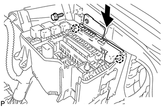
(c) Install the power distribution with the bolt.
 Removal
REMOVAL
PROCEDURE
1. REMOVE POWER DISTRIBUTION
(a) Remove the bolt.
(b) Disengage the 2 claws and disconnect the power distribution from t ...
 Main Body Ecu
Components
COMPONENTS
ILLUSTRATION
Removal
REMOVAL
PROCEDURE
1. REMOVE UPPER INSTRUMENT PANEL
HINT:
Refer to the procedure up to Remove Upper Instrument Panel Sub-assembly (See
page ) ...
Other materials about Toyota Venza:
Throttle / Pedal Position Sensor / Switch "A" Circuit Malfunction (P0120-P0123,P0220,P0222,P0223,P2135)
DESCRIPTION
HINT:
These DTCs relate to the throttle position sensor.
The throttle position sensor is mounted on the throttle body, and detects the
opening angle of the throttle valve. This sensor is a non-contact type sensor. It
uses hall-effect element ...
Data Signal Circuit between Radio Receiver and Extension Module
DESCRIPTION
The stereo component tuner assembly sends the image data signal to the radio
and display receiver assembly via this circuit.
WIRING DIAGRAM
PROCEDURE
1.
CHECK NAVIGATION WIRE
(a) Remove the navigation wire ( ...
Components
COMPONENTS
ILLUSTRATION
ILLUSTRATION
ILLUSTRATION
ILLUSTRATION
ILLUSTRATION
...

0.1338