Toyota Venza: Installation
INSTALLATION
PROCEDURE
1. INSTALL ENGINE MOUNTING DAMPER
|
(a) Install the engine mounting damper with the 3 bolts. Torque: 9.0 N·m {92 kgf·cm, 80 in·lbf} |
|
.png)
2. INSTALL WIRING HARNESS CLAMP BRACKET
|
(a) Install the bracket with the bolt. Torque: 8.4 N·m {86 kgf·cm, 74 in·lbf} |
|
.png)
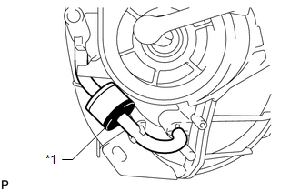
3. INSTALL CHECK VALVE
|
(a) Connect the 2 vacuum hoses to the intake manifold to install the check valve. |
|
.png)
|
(b) Check that the check valve is installed as shown in the illustration. Text in Illustration
|
|
4. INSTALL INTAKE MANIFOLD
|
(a) Close the tumble control valves. NOTICE: The tumble control valves may be damaged if they are not closed before installing the intake manifold. HINT: Connect the battery to the terminals of the actuator to operate the motor
and close the valves (See page |
|
.png)
|
(b) Install a new gasket to the intake manifold. |
|
.png)
|
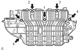
(c) Install the intake manifold by tightening the 6 bolts in the sequence shown in the illustration. Torque: 28 N·m {286 kgf·cm, 21 ft·lbf} |
|
|
(d) Connect the intake air control actuator connector. |
|
.png)
(e) Attach the 2 clamps to the intake manifold and bracket.
(f) Install the wire harness with the bolt.
Torque:
8.4 N·m {86 kgf·cm, 74 in·lbf}
|
(g) Install the wire harness bracket with the bolt. Torque: 8.4 N·m {86 kgf·cm, 74 in·lbf} |
|
.png)
(h) Connect the fuel vapor feed hose, clamp and connector.
|
(i) Install the 2 wire harness brackets with the 2 bolts. Torque: 8.4 N·m {86 kgf·cm, 74 in·lbf} |
|
.png)
5. INSTALL FUEL DELIVERY PIPE SUB-ASSEMBLY
.gif)
6. INSTALL UNION TO CONNECTOR TUBE HOSE
|
(a) Install the union to connector tube hose to the intake manifold. |
|
.png)
7. CONNECT NO. 2 VENTILATION HOSE
|
(a) Connect the No. 2 ventilation hose to the intake manifold. |
|
.png)
8. INSTALL VACUUM SWITCHING VALVE ASSEMBLY (for ACIS)
|
(a) Install the vacuum switching valve (for ACIS) with the bolt. Torque: 9.0 N·m {92 kgf·cm, 80 in·lbf} |
|
.png)
(b) Connect the 2 vacuum hoses, 2 union to connector tube hoses, clamp and connector.
9. INSTALL THROTTLE BODY ASSEMBLY
(a) Install the throttle body assembly (See page
).
10. CONNECT CABLE FROM NEGATIVE BATTERY TERMINAL
CAUTION:
When disconnecting the cable, some systems need to be initialized after the cable
is reconnected (See page ).
11. INSPECT FOR FUEL LEAK
HINT:
(See page ).
 Inspection
INSPECTION
PROCEDURE
1. INSPECT INTAKE AIR CONTROL VALVE (for ACIS)
(a) Inspect the diaphragm.
(1) Using a vacuum pump, apply a vacuum of 60 kPa (450 mmHg, 17.7 in.Hg)
or higher to ...
 Intake System
Parts Location
PARTS LOCATION
ILLUSTRATION
System Diagram
SYSTEM DIAGRAM
On-vehicle Inspection
ON-VEHICLE INSPECTION
PROCEDURE
1. INSPECT INTAKE SYSTEM
HINT:
Perform "Inspec ...
Other materials about Toyota Venza:
All Door Entry Lock/Unlock Functions do not Operate, but Wireless Functions
Operate
DESCRIPTION
When the wireless door lock and unlock functions operate, the communication circuit
between the door lock receiver assembly and certification ECU (smart key ECU assembly)
is normal. When the entry lock and unlock functions do not operate, radi ...
Diagnostic Trouble Code Chart
DIAGNOSTIC TROUBLE CODE CHART
CAN Communication System
DTC Code
Detection Item
Output ECU/Techstream Display
See page
U0100
Lost Communication with ECM / PCM
Power management ...
LIN Communication Master Malfunction (B2287)
DESCRIPTION
This DTC is stored when there is an open, short or ECU communication malfunction
between the power management control ECU and certification ECU (smart key ECU assembly).
DTC No.
DTC Detection Condition
Trouble A ...

0.1268