Toyota Venza: Installation
INSTALLATION
PROCEDURE
1. INSTALL HEATED OXYGEN SENSOR
.gif)
2. INSTALL FRONT EXHAUST PIPE ASSEMBLY
|
(a) Using a vernier caliper, measure the free length of the compression springs. Minimum Free Length: 41.5 mm (1.63 in.) If the free length is less than the minimum, replace the compression spring. |
|
.png)
(b) Temporarily install a new gasket to the exhaust manifold converter sub-assembly.
|
(c) Using a plastic hammer and wooden block, tap in the gasket until its surface is flush with the exhaust manifold converter sub-assembly. Text in Illustration
NOTICE:
|
|
.png)
|
(d) Install the front exhaust pipe assembly to the exhaust manifold converter sub-assembly with the 2 bolts and 2 compression springs. Torque: 43 N·m {438 kgf·cm, 32 ft·lbf} |
|

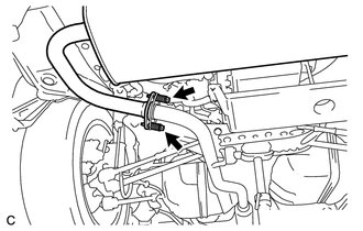
(e) Connect the heated oxygen sensor connector.
3. INSTALL CENTER EXHAUST PIPE ASSEMBLY
(a) Install a new gasket to the center exhaust pipe assembly.
(b) Connect the center exhaust pipe assembly to the 2 exhaust pipe supports.
|
(c) Install the center exhaust pipe assembly to the front exhaust pipe assembly with the 2 bolts. Torque: 43 N·m {438 kgf·cm, 32 ft·lbf} |
|

4. INSTALL TAIL EXHAUST PIPE ASSEMBLY
|
(a) Using a vernier caliper, measure the free length of the compression springs. Minimum Free Length: 38.5 mm (1.52 in.) If the free length is less than the minimum, replace the compression spring. |
|
(b) Temporarily install a new gasket to the center exhaust pipe assembly.
|
(c) Using a plastic hammer and wooden block, tap in the gasket until its surface is flush with the center exhaust pipe assembly. Text in Illustration
NOTICE:
|
|
(d) Connect the tail exhaust pipe assembly to the 4 exhaust pipe supports.
|
(e) Install the tail exhaust pipe assembly to the center exhaust pipe assembly with the 2 bolts and 2 compression springs. Torque: 43 N·m {438 kgf·cm, 32 ft·lbf} |
|
5. INSTALL TAIL EXHAUST PIPE BAFFLE SUB-ASSEMBLY
|
(a) Align the cutout of the tail exhaust pipe baffle sub-assembly with the protrusion of the tail exhaust pipe assembly as shown in the illustration. Text in Illustration
|
|

(b) Using a plastic hammer, uniformly tap the tail exhaust pipe baffle sub-assembly onto the tail exhaust pipe assembly.
6. INSPECT FOR EXHAUST GAS LEAK
If gas is leaking, tighten the areas necessary to stop the leak. Replace damaged parts as necessary.
(a) Perform "Inspection After Repair" after repairing an exhaust gas leak (See
page ).
 Components
COMPONENTS
ILLUSTRATION
...
 Removal
REMOVAL
CAUTION / NOTICE / HINT
CAUTION:
Wear protective gloves when removing the exhaust pipe.
The exhaust pipe is extremely hot immediately after the engine has stopped.
...
Other materials about Toyota Venza:
Reassembly
REASSEMBLY
CAUTION / NOTICE / HINT
HINT:
Use high-temperature grease to lubricate the bearings, gears and return spring
when assembling the starter.
PROCEDURE
1. INSTALL PLANETARY GEAR
(a) Apply grease to the planetary gears and pin parts of ...
Removal
REMOVAL
PROCEDURE
1. REMOVE AIR CONDITIONING UNIT ASSEMBLY
(See page )
2. REMOVE NO. 1 FINISH PANEL MOUNTING BRACKET
3. REMOVE NO. 2 FINISH PANEL MOUNTING BRACKET
4. REMOVE NO. 3 AIR DUCT SUB-ASSEMBLY
5. REMOVE NO. 2 AIR DUCT SUB-ASSEMBLY
...
Installation
INSTALLATION
CAUTION / NOTICE / HINT
HINT:
Use the same procedure for the LH side and RH side.
The following procedure is for the LH side.
PROCEDURE
1. INSTALL FRONT LOWER SUSPENSION ARM
(a) Install the front lower arm bushing stopper t ...

0.1204