Toyota Venza: Installation
INSTALLATION
PROCEDURE
1. INSTALL FUEL PRESSURE PULSATION DAMPER ASSEMBLY
|
(a) Apply a light coat of gasoline or spindle oil to a new O-ring. Text in Illustration
|
|
(b) Install the O-ring to the fuel pressure pulsation damper assembly.
(c) Install the fuel pressure pulsation damper assembly with the 2 bolts.
Torque:
10 N·m {102 kgf·cm, 7 ft·lbf}
NOTICE:
Make sure that the O-ring is not cracked or jammed when installing the damper.
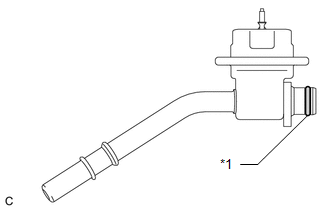
2. INSTALL FUEL TUBE SUB-ASSEMBLY
 Text in Illustration
|
*1 |
No. 2 Fuel Pipe Clamp |
|
*2 |
Fuel Hose Clamp |
.png) |
Push |
(a) Connect the fuel tube.
(b) Push the fuel tube connector until it makes a "click" sound.
(c) Install a new No. 2 fuel pipe clamp.
(d) Push the tube connector into the pipe until the tube connector makes a "click" sound.
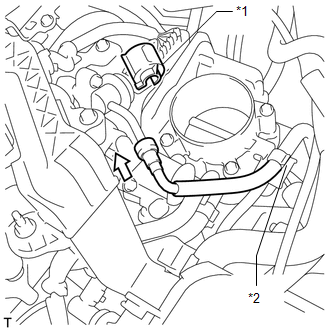
.png) Text in Illustration
Text in Illustration
|
*1 |
Fuel Pipe |
|
*2 |
Fuel Tube Connector |
|
*3 |
Nylon Tube |
|
*4 |
O-ring |
|
*5 |
Retainer |
.png) |
Push |
NOTICE:
- Before connecting the connector and fuel pipe, check that there is no damage or foreign matter on the connecting part of the fuel pipe.
- After connecting the fuel tube connector and fuel pipe, check that they are securely connected by trying to pull them apart.
(e) Install the No. 1 fuel pipe clamp.
(f) Install the fuel tube sub-assembly to the fuel hose clamp.
3. INSTALL AIR CLEANER CAP SUB-ASSEMBLY
.gif)
4. INSTALL NO. 1 VACUUM SWITCHING VALVE ASSEMBLY
5. INSTALL NO. 1 ENGINE COVER SUB-ASSEMBLY
6. INSTALL OUTER COWL TOP PANEL
7. INSTALL WINDSHIELD WIPER MOTOR AND LINK ASSEMBLY
(a) Install the windshield wiper motor and link assembly (See page
).
8. CONNECT CABLE TO NEGATIVE BATTERY TERMINAL
NOTICE:
When disconnecting the cable, some systems need to be initialized after the cable
is reconnected (See page ).
9. INSPECT FOR FUEL LEAK
 Removal
REMOVAL
PROCEDURE
1. DISCHARGE FUEL SYSTEM PRESSURE
HINT:
See page
2. DISCONNECT CABLE FROM NEGATIVE BATTERY TERMINAL
NOTICE:
When disconnecting the cable, some systems need to be initialized ...

Other materials about Toyota Venza:
Parking Brake Switch Circuit
DESCRIPTION
This circuit is from the parking brake switch assembly to the radio and display
receiver assembly.
WIRING DIAGRAM
PROCEDURE
1.
CHECK BRAKE WARNING LIGHT
(a) Check that the brake warning light comes on when t ...
System Diagram
SYSTEM DIAGRAM
Communication Table
Transmitting ECU
Receiving ECU
Signal
Communication Method
Skid control ECU
AWD control ECU
Wheel speed sensor signal
Stop ...
Front Airbag Sensor LH Malfunction (B1615/14)
DESCRIPTION
The front airbag sensor LH circuit consists of the center airbag sensor assembly
and front airbag sensor LH.
The front airbag sensor LH detects impacts to the vehicle and sends signals to
the center airbag sensor assembly to determine if the ...

0.1324