Toyota Venza: Inspection
INSPECTION
CAUTION / NOTICE / HINT
HINT:
Use the same procedure for the intake side and exhaust side.
PROCEDURE
1. INSPECT CAMSHAFT TIMING OIL CONTROL VALVE ASSEMBLY
|
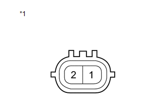
(a) Measure the resistance according to the value(s) in the table below. Standard Resistance:
If the result is not as specified, replace the oil control valve assembly. Text in Illustration
|
|
|
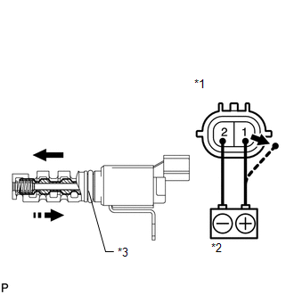
(b) Connect the positive (+) lead from a battery to terminal 1 and the negative (-) lead to terminal 2, and check the movement of the valve. OK:
NOTICE: Confirm that the valve moves freely and does not stick in any position. If necessary, replace the camshaft timing oil control valve assembly. HINT: Accumulation of foreign matter can cause minor pressure leaks. Minor pressure leaks will cause the camshaft to advance or retard, and this will cause a DTC to be set. Text in Illustration
|
|
 Removal
REMOVAL
PROCEDURE
1. REMOVE NO. 1 ENGINE COVER SUB-ASSEMBLY
2. REMOVE CAMSHAFT TIMING OIL CONTROL VALVE ASSEMBLY (for Exhaust Side)
(a) Disconnect the oil control valve connector.
...
 Installation
INSTALLATION
PROCEDURE
1. INSTALL CAMSHAFT TIMING OIL CONTROL VALVE ASSEMBLY (for Exhaust Side)
(a) Apply a light coat of engine oil to a new O-ring, and install it
to the oil contro ...
Other materials about Toyota Venza:
Accessory Meter
Components
COMPONENTS
ILLUSTRATION
Installation
INSTALLATION
PROCEDURE
1. INSTALL ACCESSORY METER ASSEMBLY (w/o Rear View Monitor System)
(a) Connect the connector.
(b) Engage the 2 clamps ...
Problem Symptoms Table
PROBLEM SYMPTOMS TABLE
HINT:
Use the table below to help determine the cause of problem symptoms. If multiple
suspected areas are listed, the potential causes of the symptoms are listed in order
of probability in the "Suspected Area" column of ...
Precaution
PRECAUTION
NOTICE:
When disconnecting the cable from the negative (-) battery terminal, initialize
the following systems after the cable is reconnected.
System Name
See Procedure
Back Door Closer System
...

0.1396