Toyota Venza: Inspection
INSPECTION
PROCEDURE
1. INSPECT FRONT DIFFERENTIAL CASE
|
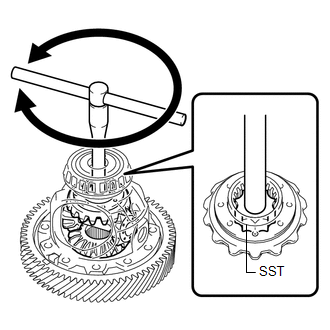
(a) Using SST, rotate the front differential side gear as shown in the illustration. SST: 09528-52010 09528-05030 Standard: The front differential side gear does not lock when rotated in either direction.
|
|
2. INSPECT FRONT DIFFERENTIAL SIDE GEAR THRUST AMOUNT
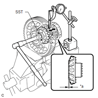
(a) Secure the front differential case in a vise between aluminum plates.
NOTICE:
Do not overtighten the vise.
|
(b) Using SST and a dial indicator, measure the front differential side gear thrust amount. Text in Illustration
SST: 09528-52010 09528-05030 Front Differential Side Gear Thrust Amount: 0.08 mm (0.00315 in.) or less HINT:
If the result is not as specified, replace the 2 front differential side gears, 2 front differential pinions and 2 conical springs. |
|
3. INSPECT FRONT DIFFERENTIAL PINION BACKLASH
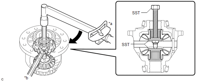
(a) Install SST as shown in the illustration and tighten it.
 Text in Illustration
|
*a |
Turn |
*b |
Hold |
SST: 09528-52010
09528-05010
09953-05010
Torque:
10 N·m {102 kgf·cm, 7 ft·lbf}
(b) Secure the front differential case in a vise between aluminum plates.
NOTICE:
Do not overtighten the vise.
|
(c) Install the front No. 1 differential pinion shaft to the front differential pinion as shown in the illustration. Text in Illustration
|
|
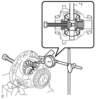
(d) Using a dial indicator, measure the front differential pinion backlash.
Standard Backlash:
0.15 mm (0.00591 in.) or less
HINT:
Select front No. 1 differential side gear thrust washers of the same thickness for both the right and left side.
If the backlash is not as specified, replace the front No. 1 differential side gear thrust washers with washers of a different thickness. Use the table below to select front No. 1 differential side gear thrust washers which will ensure that the backlash is within the specification.
Front No. 1 Differential Side Gear Thrust Washer Thickness:|
Part No. |
Thickness (mm (in.)) |
|---|---|
|
41361-06010 |
1.50 (0.0591) |
|
41361-06020 |
1.55 (0.0610) |
|
41361-06030 |
1.60 (0.0630) |
|
41361-06040 |
1.65 (0.0650) |
|
41361-06050 |
1.70 (0.0669) |
|
41361-06060 |
1.75 (0.0689) |
|
41361-06070 |
1.80 (0.0709) |
|
41361-06080 |
1.85 (0.0728) |
|
41361-06090 |
1.90 (0.0748) |
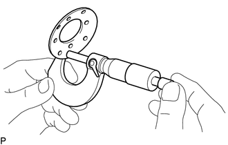
4. INSPECT FRONT DIFFERENTIAL PINION THRUST WASHER
|
(a) Using a micrometer, measure the thickness of the front differential pinion thrust washer. Minimum Thickness: 0.54 mm (0.0213 in.) HINT: Measure the most worn portion of the front differential pinion thrust washer. If the thickness is less than the minimum, replace the front differential pinion thrust washer. |
|
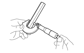
5. INSPECT FRONT NO. 1 DIFFERENTIAL PINION SHAFT
|
(a) Using a micrometer, measure the outer diameter of the front No. 1 differential pinion shaft. Minimum Outer Diameter: 20.499 mm (0.807 in.) HINT: Measure the most worn portion of the front No. 1 differential pinion shaft. If the outer diameter is less than the minimum, replace the front No. 1 differential pinion shaft. |
|
 Disassembly
DISASSEMBLY
PROCEDURE
1. REMOVE FRONT TRANSAXLE CASE OIL SEAL
(a) Using SST, remove the front transaxle case oil seal from the transaxle
housing.
SST: 09308-00010
...
 Reassembly
REASSEMBLY
PROCEDURE
1. INSTALL FRONT DIFFERENTIAL CASE REAR TAPERED ROLLER BEARING
(a) Using SST and a press, install a new front differential case rear
tapered roller bearing (inne ...
Other materials about Toyota Venza:
Replacement
REPLACEMENT
CAUTION / NOTICE / HINT
NOTICE:
Move the shift lever to P and apply the parking brake before bleeding
the brakes.
Add brake fluid to keep the level between the MIN and MAX lines of the
reservoir while bleeding the brakes.
...
Installation
INSTALLATION
PROCEDURE
1. INSTALL PARKING BRAKE PEDAL ASSEMBLY
(a) Install the parking brake pedal assembly with the 3 nuts.
Torque:
21 N·m {214 kgf·cm, 15 ft·lbf}
(b) Connect t ...
Terminals Of Ecu
TERMINALS OF ECU
1. CHECK CERTIFICATION ECU (SMART KEY ECU ASSEMBLY)
(a) Disconnect the D25 certification ECU (smart key ECU assembly) connector.
(b) Measure the voltage and resistance according to the value(s) in the table
below.
HINT:
Measure the va ...

0.1354