Toyota Venza: Inspection
INSPECTION
PROCEDURE
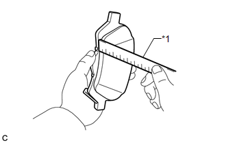
1. INSPECT PAD LINING THICKNESS
|
(a) Using a ruler, measure the pad lining thickness. Text in Illustration
Standard thickness of a new pad: 10.0 mm (0.394 in.) Minimum thickness: 1.0 mm (0.0394 in.) If the pad lining thickness is equal to or less than the minimum, replace the brake pads with a disc brake pad kit. HINT: Be sure to check the wear of the rear disc after replacing the brake pads with new ones. |
|
2. INSPECT REAR DISC BRAKE PAD SUPPORT PLATE
(a) Make sure that the rear disc brake pad support plates have sufficient rebound, no deformation, cracks or wear, and that all rust and dirt are removed. If necessary, replace the rear disc brake pad support plates.
3. INSPECT DISC THICKNESS
|
(a) Using a micrometer, measure the disc thickness. Text in Illustration
Standard Thickness of a new disc: 10.0 mm (0.394 in.) Minimum Thickness: 9.0 mm (0.354 in.) HINT: If the disc thickness is less than the minimum, replace the rear disc. |
|
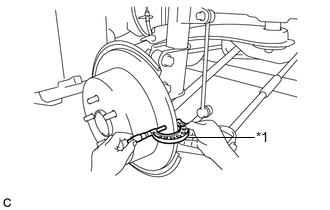
4. INSPECT DISC RUNOUT
(a) Inspect the rear axle hub bearing looseness and axle hub runout (for 2WD:
See page .gif) , for AWD: See page
).
, for AWD: See page
).
|
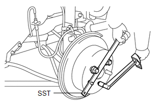
(b) Using SST to hold the disc, tighten the disc with the 5 hub nuts. SST: 09330-00021 Torque: 103 N·m {1050 kgf·cm, 76 ft·lbf} |
|
|
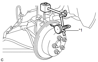
(c) Using a dial indicator, measure the disc runout 10 mm (0.394 in.) away from the outer edge of the rear disc. Text in Illustration
Maximum disc runout: 0.15 mm (0.00591 in.) If the runout exceeds the maximum, change the installation position of the disc to minimize runout. If the runout exceeds the maximum even when the installation position is changed, grind the disc. If the disc thickness is less than the minimum, replace the rear disc. NOTICE: Keep the magnetic parts of the dial indicator away from the axle hub and speed sensor. |
|
(d) Remove the 5 hub nuts and rear disc.
 Removal
REMOVAL
CAUTION / NOTICE / HINT
HINT:
Use the same procedure for the LH side and RH side.
The following procedure listed is for the LH side.
PROCEDURE
1. REMOVE REAR WHEEL
2. D ...
 Installation
INSTALLATION
PROCEDURE
1. TEMPORARILY TIGHTEN REAR DISC BRAKE BLEEDER PLUG
(a) Temporarily tighten the rear disc brake bleeder plug.
HINT:
Fully tighten the rear disc brake bleeder plug after ble ...
Other materials about Toyota Venza:
On-vehicle Inspection
ON-VEHICLE INSPECTION
CAUTION / NOTICE / HINT
HINT:
Use the same procedure for the RH side and LH side.
The procedure listed below is for the LH side.
PROCEDURE
1. REMOVE FRONT WHEEL
2. SEPARATE FRONT DISC BRAKE CALIPER ASSEMBLY
3. ...
Installation
INSTALLATION
PROCEDURE
1. INSTALL REAR SEAT INNER BELT ASSEMBLY RH
(a) Install the rear seat inner belt assembly RH with the bolt.
Torque:
42 N·m {428 kgf·cm, 31 ft·lbf}
2. INSTALL REAR SE ...
Problem Symptoms Table
PROBLEM SYMPTOMS TABLE
HINT:
Use the table below to help determine the cause of problem symptoms. If multiple
suspected areas are listed, the potential causes of the symptoms are listed in order
of probability in the "Suspected Area" column of ...

0.1636