Toyota Venza manuals

Toyota Venza: Inspection

INSPECTION

PROCEDURE

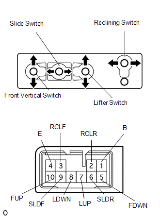
1. INSPECT FRONT POWER SEAT SWITCH LH (w/o Seat Position Memory System)

(a) Measure the resistance between the terminals when each switch is operated.

Standard Resistance:

Slide Switch

Tester Connection

Switch Condition

Specified Condition

1 (B) - 9 (SLDF)

FRONT

Below 1 Ω

4 (E) - 6 (SLDR)

FRONT

Below 1 Ω

4 (E) - 6 (SLDR)

OFF

Below 1 Ω

4 (E) - 9 (SLDF)

OFF

Below 1 Ω

1 (B) - 6 (SLDR)

REAR

Below 1 Ω

4 (E) - 9 (SLDF)

REAR

Below 1 Ω

Front Vertical Switch

Tester Connection

Switch Condition

Specified Condition

1 (B) - 10 (FUP)

UP

Below 1 Ω

4 (E) - 5 (FDWN)

UP

Below 1 Ω

4 (E) - 5 (FDWN)

OFF

Below 1 Ω

4 (E) - 10 (FUP)

OFF

Below 1 Ω

1 (B) - 5 (FDWN)

DOWN

Below 1 Ω

4 (E) - 10 (FUP)

DOWN

Below 1 Ω

Lifter Switch

Tester Connection

Switch Condition

Specified Condition

1 (B) - 7 (LUP)

UP

Below 1 Ω

4 (E) - 8 (LDWN)

UP

Below 1 Ω

4 (E) - 7 (LUP)

OFF

Below 1 Ω

4 (E) - 8 (LDWN)

OFF

Below 1 Ω

1 (B) - 8 (LDWN)

DOWN

Below 1 Ω

4 (E) - 7 (LUP)

DOWN

Below 1 Ω

Reclining Switch

Tester Connection

Switch Condition

Specified Condition

1 (B) - 3 (RCLF)

FRONT

Below 1 Ω

2 (RCLR) - 4 (E)

FRONT

Below 1 Ω

2 (RCLR) - 4 (E)

OFF

Below 1 Ω

3 (RCLF) - 4 (E)

OFF

Below 1 Ω

1 (B) - 2 (RCLR)

REAR

Below 1 Ω

3 (RCLF) - 4 (E)

REAR

Below 1 Ω

If the result is not as specified, replace the switch.


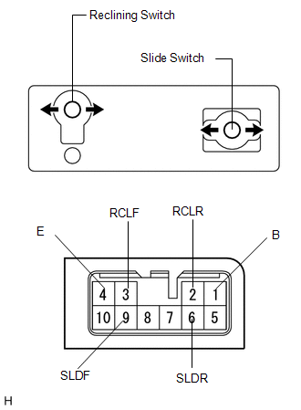
2. INSPECT FRONT POWER SEAT SWITCH RH (w/o Seat Position Memory System)

(a) Measure the resistance between the terminals when each switch is operated.

Standard Resistance:

Slide Switch

Tester Connection

Switch Condition

Specified Condition

1 (B) - 9 (SLDF)

FRONT

Below 1 Ω

4 (E) - 6 (SLDR)

FRONT

Below 1 Ω

4 (E) - 6 (SLDR)

OFF

Below 1 Ω

4 (E) - 9 (SLDF)

OFF

Below 1 Ω

1 (B) - 6 (SLDR)

REAR

Below 1 Ω

4 (E) - 9 (SLDF)

REAR

Below 1 Ω

Reclining Switch

Tester Connection

Switch Condition

Specified Condition

1 (B) - 3 (RCLF)

FRONT

Below 1 Ω

2 (RCLR) - 4 (E)

FRONT

Below 1 Ω

2 (RCLR) - 4 (E)

OFF

Below 1 Ω

3 (RCLF) - 4 (E)

OFF

Below 1 Ω

1 (B) - 2 (RCLR)

REAR

Below 1 Ω

3 (RCLF) - 4 (E)

REAR

Below 1 Ω

If the result is not as specified, replace the switch.


Removal
REMOVAL PROCEDURE 1. REMOVE FRONT SEAT HEADREST ASSEMBLY 2. REMOVE FRONT SEAT REAR OUTER TRACK COVER 3. REMOVE FRONT SEAT REAR INNER TRACK COVER 4. REMOVE FRONT SEAT ASSEMBLY 5. REMOVE ...

Installation
INSTALLATION PROCEDURE 1. INSTALL POWER SEAT SWITCH (a) Install the power seat switch with the 3 screws. (b) Connect the connector. 2. IN ...

Other materials about Toyota Venza:

Transponder Chip Malfunction (B2793)
DESCRIPTION This DTC is stored when a malfunction is found in the key during key code registration or a key code is not registered normally. Replace the key if the key code registration is not performed normally and this DTC is detected. DTC N ...

Security Horn Circuit
DESCRIPTION When the theft deterrent system is switched from the armed state to the alarm sounding state, the main body ECU (driver side junction block assembly) controls the security horn. WIRING DIAGRAM PROCEDURE 1. PERFORM A ...

Yaw Rate Sensor Communication Stop Mode
DESCRIPTION Detection Item Symptom Trouble Area Yaw Rate Sensor Communication Stop Mode "Yaw Rate/Decelerate Sensor" is not displayed on "CAN Bus Check" screen o ...

© 2016-2024 Copyright www.tovenza.com

0.1508