Toyota Venza: Inspection
INSPECTION
PROCEDURE
1. INSPECT DRIVE MONITOR SWITCH
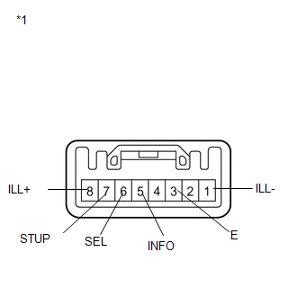
(a) Measure the resistance according to the value(s) in the table below.
Standard Resistance:
|
Tester Connection |
Condition |
Specified Condition |
|---|---|---|
|
3 (E) - 5 (INFO) |
INFO CLOCK*1 or INFO*2 switch is pressed |
Below 1 Ω |
|
3 (E) - 5 (INFO) |
INFO CLOCK*1 or INFO*2 switch is released |
10 kΩ or higher |
|
3 (E) - 6 (SEL) |
RESET H *1 or SELECT RESET*2 switch is pressed |
Below 1 Ω |
|
3 (E) - 6 (SEL) |
RESET H *1 or SELECT RESET*2 switch is released |
10 kΩ or higher |
|
3 (E) - 7 (STUP) |
US/M M*1 or SETUP*2 switch is pressed |
Below 1 Ω |
|
3 (E) - 7 (STUP) |
US/M M*1 or SETUP*2 switch is released |
10 kΩ or higher |
- *1: w/o Rear View Monitor System
- *2: w/ Rear View Monitor System
(b) Apply battery voltage from the wire harness back side between the terminals of the switch, and check the lighting condition of the drive monitor switch.
OK:
|
Measurement Condition |
Condition |
Specified Condition |
|---|---|---|
|
Battery negative (-) → 1 (ILL-) Battery positive (+) → 8 (ILL+) |
Always |
Drive monitor switch illuminates |
|
*1 |
Component without harness connected (Drive Monitor Switch) |
HINT:
If the result is not as specified, replace the drive monitor switch (See page
.gif) ).
).
 Components
COMPONENTS
ILLUSTRATION
ILLUSTRATION
ILLUSTRATION
...
 Removal
REMOVAL
PROCEDURE
1. REMOVE UPPER CONSOLE PANEL SUB-ASSEMBLY (w/o Seat Heater System)
2. REMOVE UPPER CONSOLE PANEL SUB-ASSEMBLY (w/ Seat Heater System)
3. REMOVE NO. 2 CONSOLE BOX CARPET
...
Other materials about Toyota Venza:
System Diagram
SYSTEM DIAGRAM
Communication Table
Transmitting ECU
(Transmitter)
Receiving ECU
(Receiver)
Signal
Communication Method
Combination meter
Power management control ECU
...
Problem Symptoms Table
PROBLEM SYMPTOMS TABLE
HINT:
Use the table below to help determine the cause of problem symptoms.
If multiple suspected areas are listed, the potential causes of the symptoms
are listed in order of probability in the "Suspected Area" ...
System Diagram
SYSTEM DIAGRAM
Communication Table
Transmitting ECU (Transmitter)
Receiving ECU (Receiver)
Signal
Communication Method
Certification ECU (smart key ECU assembly)
Power management contro ...

0.1708