Toyota Venza: Inspection
INSPECTION
PROCEDURE
1. INSPECT OUTER REAR VIEW MIRROR ASSEMBLY RH
(a) Check the operation of the mirror surface.
|
(1) Disconnect the outer rear view mirror assembly RH connector. |
|
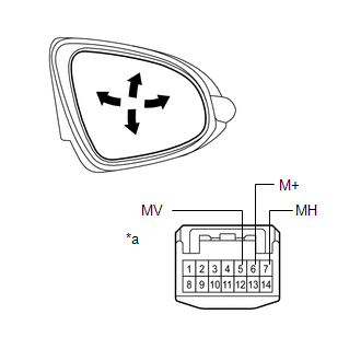
(2) Apply battery voltage and check the operation of the mirror.
OK:
|
Measurement Condition |
Specified Condition |
|---|---|
|
Battery positive (+) → Terminal 5 (MV) Battery negative (-) → Terminal 6 (M+) |
Turns upward |
|
Battery positive (+) → Terminal 6 (M+) Battery negative (-) → Terminal 5 (MV) |
Turns downward |
|
Battery positive (+) → Terminal 7 (MH) Battery negative (-) → Terminal 6 (M+) |
Turns left |
|
Battery positive (+) → Terminal 6 (M+) Battery negative (-) → Terminal 7 (MH) |
Turns right |
|
*a |
Component without harness connected (Outer Rear View Mirror Assembly RH) |
If the result is not as specified, replace the outer rear view mirror assembly RH.
(b) Check the operation of the retractable mirror. (w/ Retract Mirror)
NOTICE:
- Disconnect and reconnect the battery between each mirror position check.
- The mirror position cannot be changed manually when the battery is connected. To change the mirror position manually, the battery must be disconnected first.
|
(1) Disconnect the outer rear view mirror assembly RH connector. |
|
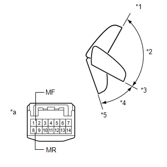
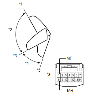
(2) For each position: Disconnect the battery, set the mirror position by hand, connect the battery, and check the retractable mirror movement.
OK:
|
Tester Connection |
Condition |
Specified Condition |
|---|---|---|
|
Battery positive (+) → Terminal 8 (MR) Battery negative (-) → Terminal 1 (MF) |
Forward position (A) |
Does not move |
|
Battery positive (+) → Terminal 1 (MF) Battery negative (-) → Terminal 8 (MR) |
Forward position (A) |
Moves from (A) to (E) |
|
Battery positive (+) → Terminal 8 (MR) Battery negative (-) → Terminal 1 (MF) |
Position between forward position (A) and driving position (C) |
Moves from (B) to (A) |
|
Battery positive (+) → Terminal 1 (MF) Battery negative (-) → Terminal 8 (MR) |
Position between forward position (A) and driving position (C) |
Moves from (B) to (E) |
|
Battery positive (+) → Terminal 8 (MR) Battery negative (-) → Terminal 1 (MF) |
Driving position (C) |
Does not move |
|
Battery positive (+) → Terminal 1 (MF) Battery negative (-) → Terminal 8 (MR) |
Driving position (C) |
Moves from (C) to (E) |
|
Battery positive (+) → Terminal 8 (MR) Battery negative (-) → Terminal 1 (MF) |
Position between driving position (C) and retracted position (E) |
Moves from (D) to (C) |
|
Battery positive (+) → Terminal 1 (MF) Battery negative (-) → Terminal 8 (MR) |
Position between driving position (C) and retracted position (E) |
Moves from (D) to (E) |
|
Battery positive (+) → Terminal 8 (MR) Battery negative (-) → Terminal 1 (MF) |
Retracted position (E) |
Moves from (E) to (C) |
|
Battery positive (+) → Terminal 1 (MF) Battery negative (-) → Terminal 8 (MR) |
Retracted position (E) |
Does not move |
|
*1 |
(A) Forward Position |
|
*2 |
(B) |
|
*3 |
(C) Driving position |
|
*4 |
(D) |
|
*5 |
(E) Retracted Position |
|
*a |
Component without harness connected (Outer Rear View Mirror Assembly RH) |
If the result is not as specified, replace the outer rear view mirror assembly RH.
(c) Check the operation of the mirror heater.
|
(1) Disconnect the outer rear view mirror assembly RH connector. |
|
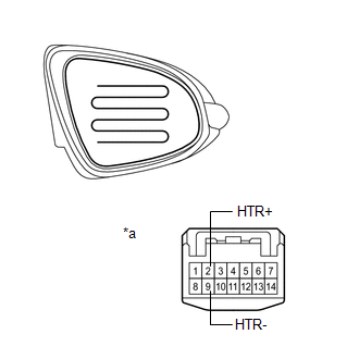
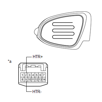
(2) Measure the resistance according to the value(s) in the table below.
Standard Resistance:
|
Tester Connection |
Condition |
Specified Condition |
|---|---|---|
|
2 (HTR+) - 9 (HTR-) |
25°C (75°F) |
7.6 to 11.4 Ω |
|
*a |
Component without harness connected (Outer Rear View Mirror Assembly RH) |
If the result is not as specified, replace the outer rear view mirror assembly RH.
(3) Connect the cable from the positive (+) terminal to terminal 2 and the negative battery (-) terminal to terminal 9, then check that the mirror becomes warm.
HINT:
It takes a short time for the mirror to become warm.
OK:
Mirror becomes warm.
If the result is not as specified, replace the outer rear view mirror assembly RH.
2. INSPECT OUTER REAR VIEW MIRROR ASSEMBLY LH
(a) Check the operation of the mirror surface.
|
(1) Disconnect the outer rear view mirror assembly LH connector. |
|
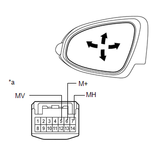
(2) Apply battery voltage and check the operation of the mirror.
OK:
|
Measurement Condition |
Specified Condition |
|---|---|
|
Battery positive (+) → Terminal 5 (MV) Battery negative (-) → Terminal 6 (M+) |
Turns upward |
|
Battery positive (+) → Terminal 6 (M+) Battery negative (-) → Terminal 5 (MV) |
Turns downward |
|
Battery positive (+) → Terminal 7 (MH) Battery negative (-) → Terminal 6 (M+) |
Turns left |
|
Battery positive (+) → Terminal 6 (M+) Battery negative (-) → Terminal 7 (MH) |
Turns right |
|
*a |
Component without harness connected (Outer Rear View Mirror Assembly LH) |
If the result is not as specified, replace the outer rear view mirror assembly LH.
(b) Check the operation of the retractable mirror. (w/ Retract Mirror)
NOTICE:
- Disconnect and reconnect the battery between each mirror position check.
- The mirror position cannot be changed manually when the battery is connected. To change the mirror position manually, the battery must be disconnected first.
|
(1) Disconnect the outer rear view mirror assembly LH connector. |
|
(2) For each position: Disconnect the battery, set the mirror position by hand, connect the battery, and check the retractable mirror movement.
OK:
|
Tester Connection |
Condition |
Specified Condition |
|---|---|---|
|
Battery positive (+) → Terminal 8 (MR) Battery negative (-) → Terminal 1 (MF) |
Forward position (A) |
Does not move |
|
Battery positive (+) → Terminal 1 (MF) Battery negative (-) → Terminal 8 (MR) |
Forward position (A) |
Moves from (A) to (E) |
|
Battery positive (+) → Terminal 8 (MR) Battery negative (-) → Terminal 1 (MF) |
Position between forward position (A) and driving position (C) |
Moves from (B) to (A) |
|
Battery positive (+) → Terminal 1 (MF) Battery negative (-) → Terminal 8 (MR) |
Position between forward position (A) and driving position (C) |
Moves from (B) to (E) |
|
Battery positive (+) → Terminal 8 (MR) Battery negative (-) → Terminal 1 (MF) |
Driving position (C) |
Does not move |
|
Battery positive (+) → Terminal 1 (MF) Battery negative (-) → Terminal 8 (MR) |
Driving position (C) |
Moves from (C) to (E) |
|
Battery positive (+) → Terminal 8 (MR) Battery negative (-) → Terminal 1 (MF) |
Position between driving position (C) and retracted position (E) |
Moves from (D) to (C) |
|
Battery positive (+) → Terminal 1 (MF) Battery negative (-) → Terminal 8 (MR) |
Position between driving position (C) and retracted position (E) |
Moves from (D) to (E) |
|
Battery positive (+) → Terminal 8 (MR) Battery negative (-) → Terminal 1 (MF) |
Retracted position (E) |
Moves from (E) to (C) |
|
Battery positive (+) → Terminal 1 (MF) Battery negative (-) → Terminal 8 (MR) |
Retracted position (E) |
Does not move |
|
*1 |
(A) Forward Position |
|
*2 |
(B) |
|
*3 |
(C) Driving position |
|
*4 |
(D) |
|
*5 |
(E) Retracted Position |
|
*a |
Component without harness connected (Outer Rear View Mirror Assembly LH) |
If the result is not as specified, replace the outer rear view mirror assembly LH.
(c) Check the operation of the mirror heater.
|
(1) Disconnect the outer rear view mirror assembly LH connector. |
|
(2) Measure the resistance according to the value(s) in the table below.
Standard Resistance:
|
Tester Connection |
Condition |
Specified Condition |
|---|---|---|
|
2 (HTR+) - 9 (HTR-) |
25°C (75°F) |
7.6 to 11.4 Ω |
|
*a |
Component without harness connected (Outer Rear View Mirror Assembly LH) |
If the result is not as specified, replace the outer rear view mirror assembly LH.
(3) Connect the cable from the positive (+) terminal to terminal 2 and the negative battery (-) terminal to terminal 8, then check that the mirror becomes warm.
HINT:
It takes a short time for the mirror to become warm.
OK:
Mirror becomes warm.
If the result is not as specified, replace the outer rear view mirror assembly LH.
 Disassembly
DISASSEMBLY
PROCEDURE
1. REMOVE OUTER MIRROR
2. REMOVE OUTER MIRROR LIGHT ASSEMBLY
3. REMOVE OUTER MIRROR COVER
4. REMOVE SIDE TURN SIGNAL LIGHT ASSEMBLY
...
 Reassembly
REASSEMBLY
PROCEDURE
1. INSTALL SIDE TURN SIGNAL LIGHT ASSEMBLY
2. INSTALL OUTER MIRROR COVER
3. INSTALL OUTER MIRROR LIGHT ASSEMBLY
4. INSTALL OUTER MIRROR
...
Other materials about Toyota Venza:
Removal
REMOVAL
PROCEDURE
1. REMOVE TAIL EXHAUST PIPE ASSEMBLY (for 1AR-FE)
2. REMOVE TAIL EXHAUST PIPE ASSEMBLY (for 2GR-FE)
3. REMOVE CENTER EXHAUST PIPE ASSEMBLY (for 1AR-FE)
4. REMOVE CENTER EXHAUST PIPE ASSEMBLY (for 2GR-FE)
5. REMOVE PROPELLER ...
Installation
INSTALLATION
PROCEDURE
1. INSTALL MANUAL VALVE
(a) Coat the manual valve with ATF and install it to the transmission
valve body assembly.
2. INSTALL TRANSMISSION VALVE BODY ASSEMBLY
(a) Coat th ...
Engine coolant
The coolant level is satisfactory if it is between the “F” and “L” lines on the
reservoir when the engine is cold.
1. Reservoir cap
2. Full
3. Low
If the level is on or below the “L” line, add coolant up to the “F” line.
- If the ...

0.1144