Toyota Venza: Inspection
INSPECTION
PROCEDURE
1. INSPECT STEERING PAD SWITCH ASSEMBLY
(a) Measure the resistance according to the value(s) in the table below.
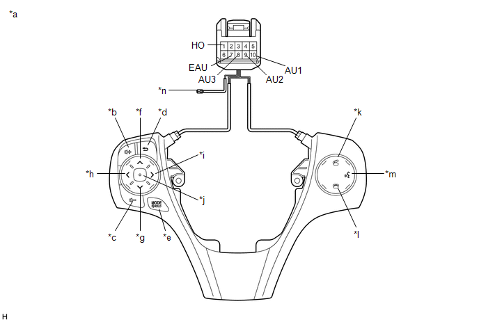
Standard Resistance:
|
Tester Connection |
Condition |
Specified Condition |
|---|---|---|
|
1 (HO) - Terminal-A |
Always |
Below 1 Ω |
|
10 (AU1) - 7 (EAU) |
No switch pushed |
95 to 105 kΩ |
|
Up switch pushed |
Below 2.5 Ω |
|
|
Down switch pushed |
313 to 345 Ω |
|
|
Volume+ switch pushed |
950 to 1050 Ω |
|
|
Volume- switch pushed |
2955 to 3265 Ω |
|
|
9 (AU2) - 7 (EAU) |
No switch pushed |
95 to 105 kΩ |
|
MODE/HOLD switch pushed |
Below 2.5 Ω |
|
|
On hook switch pushed |
313 to 345 Ω |
|
|
Off hook switch pushed |
950 to 1050 Ω |
|
|
Voice switch pushed |
2955 to 3265 Ω |
|
|
8 (AU3) - 7 (EAU) |
No switch pushed |
95 to 105 kΩ |
|
Enter switch pushed |
Below 2.5 Ω |
|
|
Back switch pushed |
313 to 345 Ω |
|
|
Right switch pushed |
950 to 1050 Ω |
|
|
Left switch pushed |
2955 to 3265 Ω |
HINT:
If the result is not as specified, replace the steering pad switch assembly.
Text in Illustration|
*a |
Component without harness connected (Steering Pad Switch Assembly) |
*b |
Volume+ |
|
*c |
Volume- |
*d |
Back |
|
*e |
MODE/HOLD |
*f |
Up |
|
*g |
Down |
*h |
Left |
|
*i |
Right |
*j |
Enter |
|
*k |
Off hook |
*l |
On hook |
|
*m |
Voice |
*n |
Terminal-A |
(b) Check the illumination.
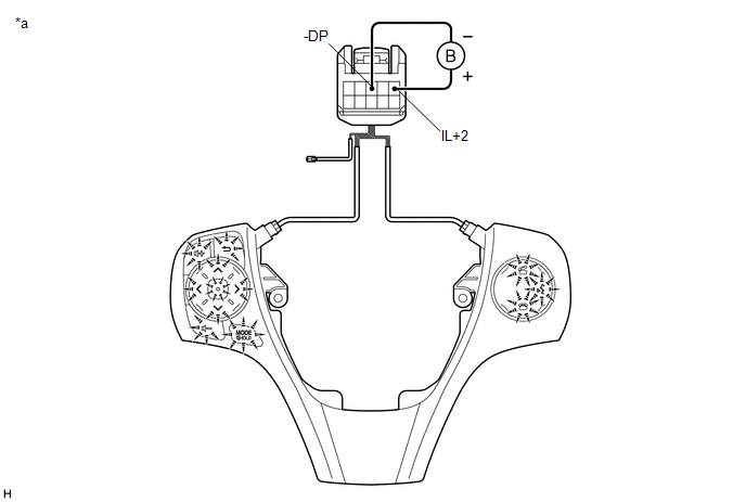
(1) Connect a battery positive (+) lead to terminal IL+2 and a negative (-) lead to terminal -DP of the steering pad switch assembly connector.
(2) Check that the switch illumination comes on.
OK:
Steering pad switch illumination comes on.
HINT:
If the result is not as specified, replace the steering pad switch assembly.
Text in Illustration|
*a |
Component without harness connected (Steering Pad Switch Assembly) |
- |
- |
 Components
COMPONENTS
ILLUSTRATION
ILLUSTRATION
...
 Removal
REMOVAL
CAUTION / NOTICE / HINT
NOTICE:
Do not replace the spiral cable with the battery connected and the ignition
switch ON.
Do not rotate the spiral cable without the steering wh ...
Other materials about Toyota Venza:
Installation
INSTALLATION
CAUTION / NOTICE / HINT
CAUTION:
The nuts must not be reused.
Make sure that the front seat frame assembly with adjuster is not deformed.
If it is, replace it with a new one.
PROCEDURE
1. INSTALL FRONT SEAT SIDE AIRBAG A ...
Lost Communication with TCM (U0101)
DESCRIPTION
The Transmission Control Module (TCM) and ECM perform 2-way communication with
each other via the Controller Area Network (CAN). The TCM sends signals to the ECM
concerning required engine speed, required engine torque, warning indicators in
...
Installation
INSTALLATION
PROCEDURE
1. TEMPORARILY TIGHTEN COMPRESSOR AND MAGNETIC CLUTCH
(a) Temporarily install the compressor and magnetic clutch and bracket
with the 4 bolts.
2. INSTALL COMPRESSOR AND MA ...

0.1315