Toyota Venza: Inspection
INSPECTION
PROCEDURE
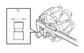
1. INSPECT GENERATOR CLUTCH PULLEY
|
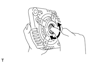
(a) Hold the generator rotor using SST, and turn the clutch pulley clockwise to check that the outer ring locks. SST: 09820-63021 Text in Illustration
If the result is not as specified, replace the clutch pulley. |
|
.png)
2. INSPECT GENERATOR DRIVE END FRAME BEARING
|
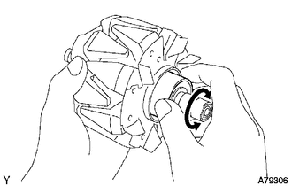
(a) Check that the bearing is not rough or worn. OK: The bearing rotates smoothly. If the bearing does not rotate smoothly, replace the bearing. |
|
3. INSPECT GENERATOR BRUSH HOLDER ASSEMBLY
|
(a) Using a vernier caliper, measure the length of the exposed brushes. Text in Illustration
Standard exposed brush length: 9.5 to 11.5 mm (0.375 to 0.452 in.) Minimum exposed brush length: 4.5 mm (0.178 in.) If the exposed brush length is less than the minimum, replace the brush holder assembly. |
|
.png)
4. INSPECT GENERATOR ROTOR ASSEMBLY
|
(a) Check that the generator rotor bearing is not rough or worn. If necessary, replace the generator rotor assembly. |
|
|
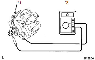
(b) Check the generator rotor for an open circuit. Text in Illustration
(1) Using an ohmmeter, measure the resistance between the slip rings. Standard Resistance:
If the result is not as specified, replace the generator rotor assembly. |
|
||||||||||||||
|
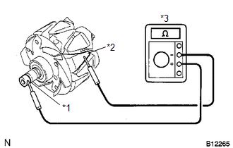
(c) Check the rotor for a short to ground. Text in Illustration
(1) Using an ohmmeter, measure the resistance between the slip ring and rotor. Standard Resistance:
If the result is not as specified, replace the generator rotor assembly. |
|
|
(d) Using a vernier caliper, measure the slip ring diameter. Text in Illustration
Standard diameter: 14.2 to 14.4 mm (0.560 to 0.566 in.) Minimum diameter: 14.0 mm (0.552 in.) If the diameter is less than the minimum, replace the generator rotor assembly. |
|
 Disassembly
DISASSEMBLY
PROCEDURE
1. REMOVE GENERATOR REAR END COVER
(a) Remove the 3 nuts and generator rear end cover.
2. REMOVE TERMINAL INSULATOR
...
 Replacement
REPLACEMENT
PROCEDURE
1. REPLACE GENERATOR DRIVE END FRAME BEARING
(a) Remove the 4 screws and bearing retainer from the drive end frame.
...
Other materials about Toyota Venza:
Diagnosis System
DIAGNOSIS SYSTEM
1. DESCRIPTION
(a) The certification ECU (smart key ECU assembly) control the vehicle smart
key system functions. Smart key system data and Diagnostic Trouble Codes (DTCs)
can be read through the vehicle Data Link Connector 3 (DLC3). In ...
Removal
REMOVAL
PROCEDURE
1. REMOVE AUTOMATIC TRANSAXLE ASSEMBLY
HINT:
See the steps from "Remove Engine Assembly with transaxle" through "Remove Automatic
Transaxle Assembly" (See page ).
2. REMOVE AUTOMATIC TRANSAXLE OIL PAN SUB-ASSEMBLY
...
Installation
INSTALLATION
PROCEDURE
1. INSTALL NO. 3 PARKING BRAKE CABLE ASSEMBLY
(a) Install the No. 3 parking brake cable assembly with the bolt and 4 nuts.
Torque:
Nut (A) :
5.4 N·m {55 kgf·cm, 48 in·lbf}
Nut (B) :
6.0 N·m {61 kgf·cm, 53 in·lbf}
Bolt ...

0.1605