Toyota Venza: Inspection
INSPECTION
PROCEDURE
1. INSPECT FUEL INJECTOR ASSEMBLY
|
(a) Measure the resistance according to the value(s) in the table below. Standard Resistance:
If the result is not as specified, replace the fuel injector assembly. |
|

(b) Inspect the injector injection.
CAUTION:
Keep the injector away from sparks during the test.
|
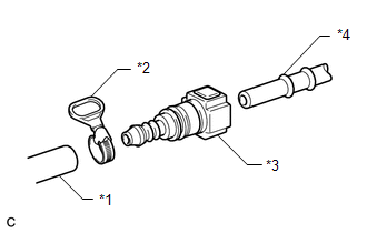
(1) Connect SST (fuel tube connector) to SST (hose) with SST (hose band), and then connect them to the fuel pipe (vehicle side). Text in Illustration
SST: 09268-31014 09268-41500 09268-41700 95336-08070 |
|
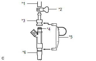
(2) Install a new O-ring to the fuel injector assembly.
|
(3) Connect SST (adapter and hose) to the fuel injector assembly, and hold the fuel injector assembly and union with SST (clamp). Text in Illustration
SST: 09268-31014 09268-41110 09268-41300 09268-41700 95336-08070 |
|
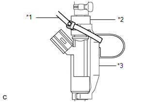
(4) Install a vinyl tube onto the fuel injector assembly.
CAUTION:
Install a suitable vinyl tube onto the injector to contain any gasoline spray.
|
(5) Tie the clamp and adapter together with SST (tie band) as shown in the illustration. Text in Illustration
SST: 09268-31014 09268-41110 09268-41300 09268-41800 |
|
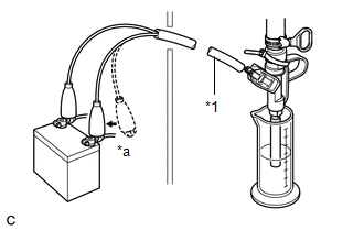
(6) Put the fuel injector assembly into a graduated cylinder.
(7) Operate the fuel pump (See page .gif) ).
).
|
(8) Connect SST (wire) to the fuel injector assembly and the battery for 15 seconds, and measure the injection volume with the graduated cylinder. Test each fuel injector assembly 2 or 3 times. Text in Illustration
SST: 09842-30080 Standard Injection Volume:
Standard difference between each fuel injector assembly: 18 cc (1.1 cu. in.) or less If the result is not as specified, replace the fuel injector assembly. |
|
(c) Check for fuel drop.
(1) In the condition above, disconnect the tester probes of SST (wire) from the battery and check for fuel drop from the fuel injector assembly.
Standard fuel drop:
1 drop or less per 20 minutes
If fuel drop is not as specified, replace the fuel injector assembly.
 Removal
REMOVAL
CAUTION / NOTICE / HINT
HINT:
Perform "Inspection After Repair" after replacing the fuel injector assembly
(See page ).
PROCEDURE
1. DISCHARGE FUEL SYSTEM PRESSURE
(a) Disch ...
 Installation
INSTALLATION
PROCEDURE
1. INSTALL FUEL INJECTOR ASSEMBLY
HINT:
Perform "Inspection After Repair" after replacing the fuel injector assembly
(See page ).
(a) Apply a light ...
Other materials about Toyota Venza:
Removal
REMOVAL
CAUTION / NOTICE / HINT
HINT:
Use the same procedure for the LH side and RH side.
The following procedure is for the LH side.
If the sensor rotor needs to be replaced, replace it together with the
rear drive shaft assembly.
...
Installation
INSTALLATION
CAUTION / NOTICE / HINT
HINT:
Perform "Inspection After Repair" after replacing the engine assembly (See page
).
PROCEDURE
1. INSTALL ENGINE HANGERS
2. REMOVE ENGINE STAND
(a) Remove the engine stand.
3. INSTALL ENGINE WIRE
...
Driver Side Power Mirror cannot be Adjusted with Power Mirror Switch
SYSTEM DESCRIPTION
When the mirror adjust switch is operated, the main body ECU (driver side junction
block assembly) detects the switch operation and sends the mirror adjust switch
signal to the outer mirror control ECU assembly (driver door) via CAN com ...

0.1656