Toyota Venza: IG Signal Circuit
DESCRIPTION
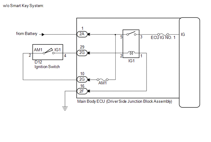
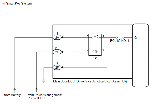
This circuit detects the ignition switch ON or off condition, and sends it to the main body ECU (driver side junction block assembly).
WIRING DIAGRAM
CAUTION / NOTICE / HINT
NOTICE:
Inspect the fuses for circuits related to this system before performing the following inspection procedure.
PROCEDURE
|
1. |
READ VALUE USING TECHSTREAM |
(a) Connect the Techstream to the DLC3.
(b) Turn the ignition switch to ON.
(c) Turn the Techstream on.
(d) Enter the following menus: Body Electrical / Main Body / Data List.
(e) Read the display on the Techstream.
Main Body|
Tester Display |
Measurement Item/Range |
Normal Condition |
Diagnostic Note |
|---|---|---|---|
|
IG SW |
Ignition switch or engine switch IG signal/ON or OFF |
ON: Ignition switch ON OFF: Ignition switch off |
- |
OK:
Normal conditions listed above are displayed.
| OK | .gif) |
PROCEED TO NEXT SUSPECTED AREA SHOWN IN PROBLEM SYMPTOMS TABLE |
|
.gif)
|
2. |
INSPECT NO. 1 IGNITION RELAY |
|
(a) Remove the No. 1 ignition relay from the main body ECU (driver side junction block assembly). |
|
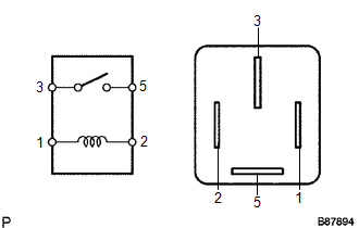
(b) Measure the resistance according to the value(s) in the table below.
Standard Resistance:
|
Tester Connection |
Condition |
Specified Condition |
|---|---|---|
|
3 - 5 |
When battery voltage is not applied to terminals 1 and 2 |
10 kΩ or higher |
|
When battery voltage is applied to terminals 1 and 2 |
Below 1 Ω |
| NG | |
REPLACE NO. 1 IGNITION RELAY |
|
|
3. |
CHECK HARNESS AND CONNECTOR (MAIN BODY ECU - BATTERY AND BODY GROUND) |
|
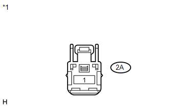
(a) Disconnect the 2A main body ECU (driver side junction block assembly) connector. |
|
(b) Measure the voltage according to the value(s) in the table below.
Standard Voltage:
|
Tester Connection |
Condition |
Specified Condition |
|---|---|---|
|
2A-1 - Body ground |
Always |
10 to 14 V |
|
*1 |
Front view of wire harness connector (to Main Body ECU (Driver Side Junction Block Assembly)) |
|
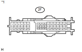
(c) Disconnect the 2F main body ECU (driver side junction block assembly) connector. |
|
(d) Measure the resistance according to the value(s) in the table below.
Standard Resistance:
|
Tester Connection |
Condition |
Specified Condition |
|---|---|---|
|
2F-16 - Body ground |
Always |
Below 1 Ω |
|
*1 |
Front view of wire harness connector (to Main Body ECU (Driver Side Junction Block Assembly)) |
| NG | |
REPAIR OR REPLACE HARNESS OR CONNECTOR |
|
|
4. |
CHECK VEHICLE CONDITION |
(a) Check the vehicle condition.
|
Condition |
Proceed to |
|---|---|
|
w/o Smart Key System |
A |
|
w/ Smart Key System |
B |
| B | |
GO TO STEP 7 |
|
|
5. |
CHECK HARNESS AND CONNECTOR (MAIN BODY ECU - IGNITION SWITCH) |
|
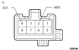
(a) Disconnect the D12 ignition switch connector. |
|
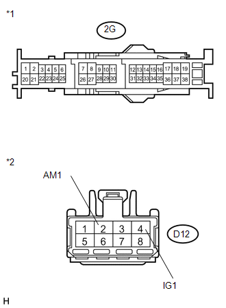
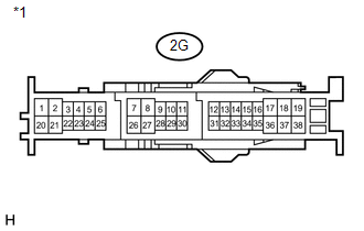
(b) Disconnect the 2G main body ECU (driver side junction block assembly) connector.
(c) Measure the resistance according to the value(s) in the table below.
Standard Resistance:
|
Tester Connection |
Condition |
Specified Condition |
|---|---|---|
|
2G-10 - D12-2 (AM1) |
Always |
Below 1 Ω |
|
2G-29 - D12-4 (IG1) |
Always |
Below 1 Ω |
|
2G-10 - Body ground |
Always |
10 kΩ or higher |
|
2G-29 - Body ground |
Always |
10 kΩ or higher |
|
*1 |
Front view of wire harness connector (to Main Body ECU (Driver Side Junction Block Assembly)) |
|
*2 |
Front view of wire harness connector: (to Ignition Switch) |
| NG | |
REPAIR OR REPLACE HARNESS OR CONNECTOR |
|
|
6. |
INSPECT IGNITION SWITCH |
|
(a) Measure the resistance according to the value(s) in the table below. Standard Resistance:
|
|
| OK | |
REPLACE MAIN BODY ECU (DRIVER SIDE JUNCTION BLOCK ASSEMBLY) |
| NG | |
REPLACE IGNITION SWITCH |
|
7. |
CHECK HARNESS AND CONNECTOR (POWER MANAGEMENT CONTROL ECU - MAIN BODY ECU) |
|
(a) Disconnect the 2G main body ECU (driver side junction block assembly) connector. |
|
(b) Measure the voltage according to the value(s) in the table below.
Standard Voltage:
|
Tester Connection |
Condition |
Specified Condition |
|---|---|---|
|
2G-29 - Body ground |
Engine switch on (IG) |
11 to 14 V |
|
*1 |
Front view of wire harness connector (to Main Body ECU (Driver Side Junction Block Assembly)) |
| OK | |
REPLACE MAIN BODY ECU (DRIVER SIDE JUNCTION BLOCK ASSEMBLY) |
| NG | |
REPAIR OR REPLACE HARNESS OR CONNECTOR |
 Data List / Active Test
DATA LIST / ACTIVE TEST
1. DATA LIST
HINT:
Using the Techstream to read the Data List allows the values or states of switches,
sensors, actuator and other items to be read without removing any pa ...
 ACC Signal Circuit
DESCRIPTION
This circuit detects the ignition switch ACC or off condition, and sends it to
the main body ECU (driver side junction block assembly).
WIRING DIAGRAM
CAUTION / NOTICE / HINT
NOT ...
Other materials about Toyota Venza:
Removal
REMOVAL
CAUTION / NOTICE / HINT
HINT:
Use the same procedure for the LH side and RH side.
The following procedure is for the LH side.
If the sensor rotor needs to be replaced, replace it together with the
front drive shaft assembly.
...
System Description
SYSTEM DESCRIPTION
1. FUNCTION OF MAIN COMPONENTS
Component
Function
Accessory Meter Assembly
AWD Warning Light
Illuminates to warn the driver of a malfunction in the active
torque ...
Fail-safe Chart
FAIL-SAFE CHART
1. POWER WINDOW OPERATION IN FAIL-SAFE MODE
HINT:
If the pulse sensor built into the power window regulator motor malfunctions,
the power window control system enters fail-safe mode.
(a) The power window control system prohibits the follo ...

0.1517