Toyota Venza: High Mounted Stop Light Assembly
Components
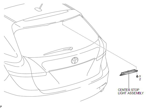
COMPONENTS
ILLUSTRATION
Removal
REMOVAL
PROCEDURE
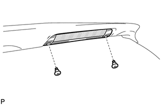
1. REMOVE CENTER STOP LIGHT ASSEMBLY
|
(a) Using a short screwdriver, remove the 2 screws. |
|
(b) Disconnect the connector and remove the center stop light assembly.
Inspection
INSPECTION
PROCEDURE
1. INSPECT CENTER STOP LIGHT ASSEMBLY
|
(a) Connect a positive (+) lead from the battery to terminal 2 and a negative (-) lead to terminal 1. |
|
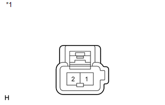
(b) Check that the light comes on.
OK:
The light comes on.
Text in Illustration|
*1 |
Component without harness connected (Center Stop Light Assembly) |
If the result is not as specified, replace the center stop light assembly.
Installation
INSTALLATION
PROCEDURE
1. INSTALL CENTER STOP LIGHT ASSEMBLY
(a) Connect the connector.
|
(b) Using a short screwdriver, install the center stop light assembly with the 2 screws. |
|
.png)
 Removal
REMOVAL
CAUTION / NOTICE / HINT
PROCEDURE
1. PRECAUTION
NOTICE:
After turning the ignition switch off, waiting time may be required before disconnecting
the cable from the negative (-) battery ...
 License Plate Light Assembly
Components
COMPONENTS
ILLUSTRATION
ILLUSTRATION
Installation
INSTALLATION
PROCEDURE
1. INSTALL LICENSE PLATE LIGHT ASSEMBLY
(a) Engage the 2 claws to install the license pla ...
Other materials about Toyota Venza:
Removal
REMOVAL
CAUTION / NOTICE / HINT
HINT:
Use the same procedure for the RH side and LH side.
The procedure listed below is for the LH side.
PROCEDURE
1. DISCONNECT CABLE FROM NEGATIVE BATTERY TERMINAL
CAUTION:
Wait at least 90 seconds aft ...
GCWR, TWR and Unbraked TWR
Confirm that the gross trailer weight, gross combination weight, gross vehicle
weight, gross axle weight and tongue weight are all within the limits.
- GCWR* and TWR*
► Vehicles without towing package
► Vehicles with towing package
...
System Description
SYSTEM DESCRIPTION
1. POWER BACK DOOR SYSTEM DESCRIPTION
(a) The power back door system controls the power back door by automatically
opening and closing the power back door with a motor.
(1) The power back door system operates only when the necessary con ...

0.1462