Toyota Venza: Height Control Sensor
Components
COMPONENTS
ILLUSTRATION
ILLUSTRATION
Removal
REMOVAL
PROCEDURE
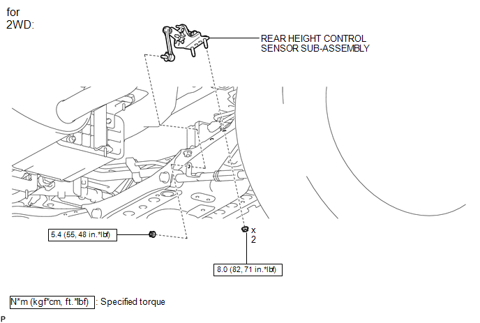
1. REMOVE REAR HEIGHT CONTROL SENSOR SUB-ASSEMBLY (for 2WD)
|
(a) Disconnect the connector. |
|
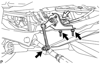
(b) Remove the 3 nuts and rear height control sensor sub-assembly.
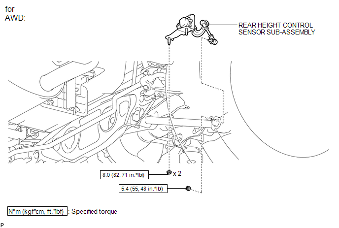
2. REMOVE REAR HEIGHT CONTROL SENSOR SUB-ASSEMBLY (for AWD)
|
(a) Disconnect the connector. |
|
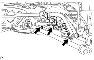
(b) Remove the 3 nuts and rear height control sensor sub-assembly.
Inspection
INSPECTION
PROCEDURE
1. INSPECT REAR HEIGHT CONTROL SENSOR SUB-ASSEMBLY RH (for 2WD)
|
(a) Connect 3 dry cell batteries (1.5 V) in series. |
|
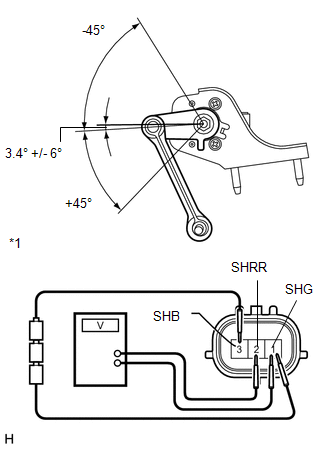
(b) Connect a positive (+) lead from the batteries to terminal 3 (SHB) and a negative (-) lead from the batteries to terminal 1 (SHG).
(c) Measure the voltage between terminals 2 (SHRR) and 1 (SHG) while slowly moving the link up and down.
Standard Voltage:
|
Tester Connection |
Condition |
Specified Condition |
|---|---|---|
|
2 (SHRR) - 1 (SHG) |
+45° (High) |
4.05 V |
|
2 (SHRR) - 1 (SHG) |
0° (normal) |
2.25 V |
|
2 (SHRR) - 1 (SHG) |
-45° (Low) |
0.45 V |
|
*1 |
Component without harness connected (Rear Height Control Sensor Sub-assembly RH) |
If the result is not as specified, replace the rear height control sensor sub-assembly RH.
2. INSPECT REAR HEIGHT CONTROL SENSOR SUB-ASSEMBLY RH (for AWD)
|
(a) Connect 3 dry cell batteries (1.5 V) in series. |
|
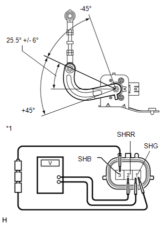
(b) Connect a positive (+) lead from the batteries to terminal 3 (SHB) and a negative (-) lead from the batteries to terminal 1 (SHG).
(c) Measure the voltage between terminals 2 (SHRR) and 1 (SHG) while slowly moving the link up and down.
Standard Voltage:
|
Tester Connection |
Condition |
Specified Condition |
|---|---|---|
|
2 (SHRR) - 1 (SHG) |
+45° (High) |
4.05 V |
|
2 (SHRR) - 1 (SHG) |
0° (normal) |
2.25 V |
|
2 (SHRR) - 1 (SHG) |
-45° (Low) |
0.45 V |
|
*1 |
Component without harness connected (Rear Height Control Sensor Sub-assembly RH) |
If the result is not as specified, replace the rear height control sensor sub-assembly RH.
Installation
INSTALLATION
PROCEDURE
1. INSTALL REAR HEIGHT CONTROL SENSOR SUB-ASSEMBLY (for 2WD)
|
(a) Install the rear height control sensor sub-assembly with the 3 nuts. Torque: Nut (A) : 8.0 N·m {82 kgf·cm, 71 in·lbf} Nut (B) : 5.4 N·m {55 kgf·cm, 48 in·lbf} |
|
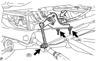
(b) Connect the connector.
2. INSTALL REAR HEIGHT CONTROL SENSOR SUB-ASSEMBLY (for AWD)
|
(a) Install the rear height control sensor sub-assembly with the 3 nuts. Torque: Nut (A) : 8.0 N·m {82 kgf·cm, 71 in·lbf} Nut (B) : 5.4 N·m {55 kgf·cm, 48 in·lbf} |
|
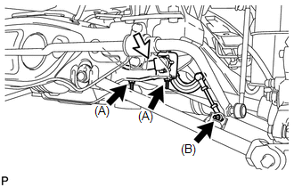
(b) Connect the connector.
3. HEIGHT CONTROL SENSOR SIGNAL INITIALIZATION
(See page .gif) )
)
4. PREPARE VEHICLE FOR HEADLIGHT AIM ADJUSTMENT
5. PREPARE FOR HEADLIGHT AIMING
6. INSPECT HEADLIGHT AIMING
7. ADJUST HEADLIGHT AIMING
 Headlight Leveling Ecu
Components
COMPONENTS
ILLUSTRATION
Removal
REMOVAL
PROCEDURE
1. REMOVE HEADLIGHT LEVELING ECU ASSEMBLY
(a) Disconnect the connector.
...

Other materials about Toyota Venza:
Front Crankshaft Oil Seal
Components
COMPONENTS
ILLUSTRATION
Removal
REMOVAL
PROCEDURE
1. REMOVE FRONT WHEEL RH
2. REMOVE NO. 1 ENGINE UNDER COVER
3. SEPARATE FRONT FENDER LINER RH
4. REMOVE FRONT FENDER APRON SEAL RH
5. REMOVE V-RIBBED BELT
6. REMOVE CRANKSHAFT ...
Intake Manifold Runner Control Stuck Open (Bank 1) (P2004,P2006)
DESCRIPTION
The tumble control valve is built into the intake manifold. The tumble control
valve is composed of a position sensor and a DC motor. The DC motor opens and closes
the tumble control valve in response to signals from the ECM. The position sens ...
Air Mix Damper Control Servo Motor Circuit (Passenger Side) (B1441/41)
DESCRIPTION
The air mix control servo motor sends pulse signals to indicate the damper position
to the A/C amplifier. The A/C amplifier activates the motor (normal or reverse)
based on these signals to move the air mix damper (front passenger side) to any ...

0.1384