Toyota Venza: Heated Oxygen Sensor
Components
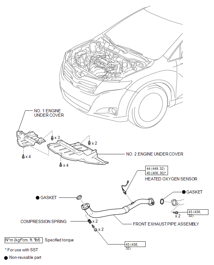
COMPONENTS
ILLUSTRATION
Removal
REMOVAL
PROCEDURE
1. REMOVE NO. 1 ENGINE UNDER COVER
2. REMOVE NO. 2 ENGINE UNDER COVER
3. REMOVE FRONT EXHAUST PIPE ASSEMBLY
.gif)
4. REMOVE HEATED OXYGEN SENSOR
|
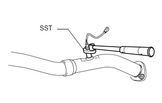
(a) Using SST, remove the heated oxygen sensor from the front exhaust pipe assembly. SST: 09224-00011 |
|
Inspection
INSPECTION
PROCEDURE
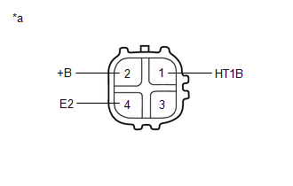
1. INSPECT HEATED OXYGEN SENSOR
|
(a) Measure the resistance according to the value(s) in the table below. Text in Illustration
Standard Resistance:
If the result is not as specified, replace the heated oxygen sensor. |
|
Installation
INSTALLATION
PROCEDURE
1. INSTALL HEATED OXYGEN SENSOR
HINT:
Perform "Inspection After Repair" after replacing the heated oxygen sensor (See
page .gif) ).
).
|
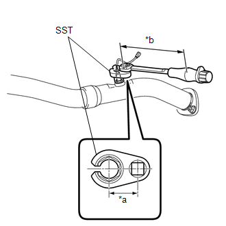
(a) Using SST, install the heated oxygen sensor to the front exhaust pipe assembly. Text in Illustration
SST: 09224-00011 Torque: without SST [Torque (N*m (kgf*cm, ft.*lbf))] : 44 N·m {449 kgf·cm, 32 ft·lbf} with SST [Reading of Torque wrench (N*m (kgf*cm, ft.*lbf))] : 40 N·m {408 kgf·cm, 30 ft·lbf} NOTICE: If the heated oxygen sensor has been struck or dropped, replace it. HINT:
|
|
2. INSTALL FRONT EXHAUST PIPE ASSEMBLY
3. INSPECT FOR EXHAUST GAS LEAK
4. INSTALL NO. 2 ENGINE UNDER COVER
5. INSTALL NO. 1 ENGINE UNDER COVER
6. PERFORM INITIALIZATION
(a) Perform "Inspection After Repair" after replacing the heated oxygen sensor
(See page ).
 Installation
INSTALLATION
PROCEDURE
1. INSTALL ENGINE COOLANT TEMPERATURE SENSOR
(a) Install a new gasket to the sensor.
Text in Illustration
*1
New Gasket
...
 Ignition Coil And Spark Plug
Components
COMPONENTS
ILLUSTRATION
Removal
REMOVAL
PROCEDURE
1. REMOVE NO. 1 ENGINE COVER SUB-ASSEMBLY
2. REMOVE IGNITION COIL ASSEMBLY
(a) Disconnect the 4 ignition coil assembly con ...
Other materials about Toyota Venza:
Illumination Circuit
DESCRIPTION
Power is supplied to the navigation receiver assembly and steering pad switch
assembly illumination when the light control switch is in the tail or head position.
WIRING DIAGRAM
CAUTION / NOTICE / HINT
NOTICE:
The vehicle is equipp ...
Cup holders
► Front
► Rear
Pull down the armrest and open the lid.
- Adjusting size of the front cup holder
Remove the adapter.
CAUTION
- Items unsuitable for the cup holder
Do not place anything other than cups or aluminum cans in the ...
Horn
Components
COMPONENTS
ILLUSTRATION
Inspection
INSPECTION
PROCEDURE
1. INSPECT LOW PITCHED HORN ASSEMBLY
(a) Apply battery voltage and check the operation of the low pitched
horn assembly according to the table below.
OK:
...

0.1738