Toyota Venza: Headlight Dimmer Switch
Components
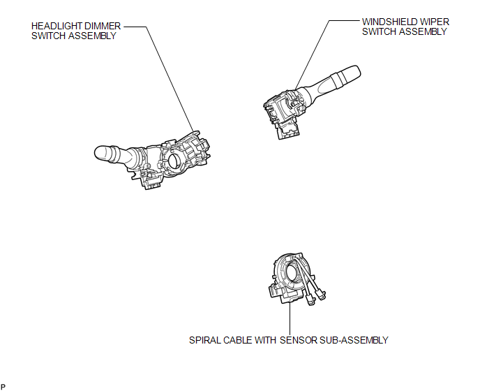
COMPONENTS
ILLUSTRATION
Removal
REMOVAL
PROCEDURE
1. REMOVE SPIRAL CABLE WITH SENSOR SUB-ASSEMBLY
(See page .gif) )
)
2. REMOVE WINDSHIELD WIPER SWITCH ASSEMBLY
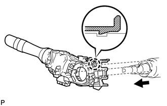
3. REMOVE HEADLIGHT DIMMER SWITCH ASSEMBLY
|
(a) Disconnect the connector. |
|

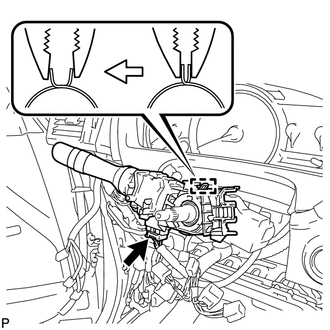
(b) Disengage the clamp as shown in the illustration.
|
(c) Disengage the claw and remove the headlight dimmer switch assembly as shown in the illustration. |
|
Inspection
INSPECTION
PROCEDURE
1. INSPECT HEADLIGHT DIMMER SWITCH ASSEMBLY
|
(a) Measure the resistance according to the value(s) in the table below. Standard Resistance: Light Control Switch
If the result is not as specified, replace the headlight dimmer switch assembly. |
|
Installation
INSTALLATION
PROCEDURE
1. INSTALL HEADLIGHT DIMMER SWITCH ASSEMBLY
|
(a) Install the headlight dimmer switch assembly as shown in the illustration. |
|
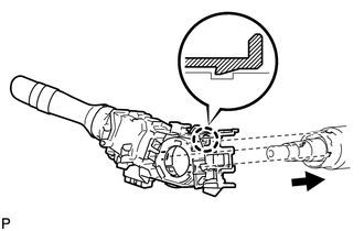
(b) Engage the claw.
|
(c) Install the headlight dimmer switch assembly with the clamp. |
|
(d) Connect the connector.
2. INSTALL WINDSHIELD WIPER SWITCH ASSEMBLY
.gif)
3. INSTALL SPIRAL CABLE WITH SENSOR SUB-ASSEMBLY
(See page )
 Installation
INSTALLATION
PROCEDURE
1. INSTALL HEADLIGHT ASSEMBLY
(a) Connect each connector.
(b) Install the headlight assembly with the bolt and 3 screws.
Torque:
3.6 N·m {37 kgf·cm, 32 in·lbf}
2. INS ...
 Headlight Leveling Ecu
Components
COMPONENTS
ILLUSTRATION
Removal
REMOVAL
PROCEDURE
1. REMOVE HEADLIGHT LEVELING ECU ASSEMBLY
(a) Disconnect the connector.
...
Other materials about Toyota Venza:
Differential System
Precaution
PRECAUTION
Before disassembly, clean the outside of the differential assembly and
remove any sand or mud to prevent it from entering the inside of the assembly
during disassembly and installation.
When removing an installed pa ...
Installation
INSTALLATION
CAUTION / NOTICE / HINT
NOTICE:
When disconnecting the steering intermediate shaft assembly and pinion shaft
of steering gear assembly, be sure to place matchmarks before servicing.
PROCEDURE
1. INSTALL TIE ROD ASSEMBLY LH
(a) I ...
Inspection
INSPECTION
PROCEDURE
1. INSPECT REAR POWER WINDOW REGULATOR MOTOR ASSEMBLY LH
(a) Apply positive (+) battery voltage to connector terminal 2 (B).
NOTICE:
Do not apply positive (+) battery voltage to any terminals other than
terminal 2 ( ...

0.1808