Toyota Venza: Gauges and meters
►Vehicles with smart key system The following gauges, meters and display illuminate when the “ENGINE START STOP” switch is in IGNITION ON mode.
►Vehicles without smart key system The following gauges, meters and displays illuminate when the engine switch is in the “ON” position.
1. Tachometer
Displays the engine speed in revolutions per minute.
2. Speedometer
Displays the vehicle speed.
3. Fuel gauge
Displays the quantity of fuel remaining in the tank.
4. Engine coolant temperature gauge Displays the engine coolant temperature.
5. Odometer/trip meter and trip meter reset button Switches between odometer and trip meter displays. Pushing and holding the button will reset the trip meter when the trip meter is being displayed.
6. Odometer and trip meter Odometer: Displays the total distance the vehicle has been driven.
Trip meter: Displays the distance the vehicle has been driven since the meter was last reset. Trip meters A and B can be used to record and display different distances independently.
Instrument panel light control
The brightness of the instrument panel lights can be adjusted.
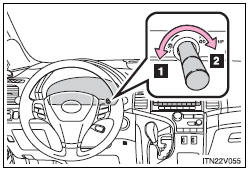
1. Darker
2. Brighter
NOTICE
- To prevent damage to the engine and its components
• Do not let the indicator needle of the tachometer enter the red zone, which indicates the maximum engine speed.
• The engine may be overheating if the engine coolant temperature gauge is in the red zone (“H”). In this case, immediately stop the vehicle in a safe place, and check the engine after it has cooled completely.

 Indicators and warning lights
The indicator and warning lights on the instrument cluster and center panel
inform the driver of the status of the vehicle’s various systems.
For the purpose of explanation, the following illustr ...
Other materials about Toyota Venza:
Removal
REMOVAL
PROCEDURE
1. REMOVE WHEEL ASSEMBLY
2. REMOVE TIRE PRESSURE WARNING VALVE AND TRANSMITTER
(a) Remove the tire valve cap.
NOTICE:
Keep the removed tire valve cap.
(b) Remove the valve core to release the air from the tire.
NOTICE:
Make sure that ...
Amplifier Antenna
Components
COMPONENTS
ILLUSTRATION
Removal
REMOVAL
PROCEDURE
1. REMOVE BACK DOOR PANEL TRIM ASSEMBLY
2. REMOVE AMPLIFIER ANTENNA ASSEMBLY
(a) Disconnect the 2 connectors.
(b) Remove th ...
Wireless-linked Return Function does not Operate
DESCRIPTION
When a door is unlocked using the wireless unlock function or entry unlock function,
the certification ECU (smart key ECU assembly) sends a door unlock signal and key
ID signal to the main body ECU (driver side junction block assembly). When t ...

0.1153