Toyota Venza: Fuel Sender Gauge Assembly
Components
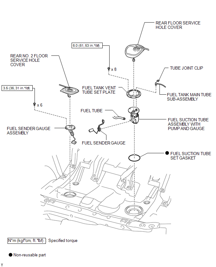
COMPONENTS
ILLUSTRATION
Removal
REMOVAL
PROCEDURE
1. DISCHARGE FUEL SYSTEM PRESSURE
(a) Discharge fuel system pressure (See page
.gif) ).
).
2. DISCONNECT CABLE FROM NEGATIVE BATTERY TERMINAL
NOTICE:
When disconnecting the cable, some systems need to be initialized after the cable
is reconnected (See page ).
3. REMOVE FUEL SUCTION TUBE ASSEMBLY WITH PUMP AND GAUGE
(a) Remove the fuel suction tube assembly with pump and gauge (See page
).
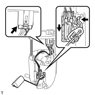
4. REMOVE FUEL SENDER GAUGE
|
(a) Disconnect the fuel sender gauge connector from the fuel suction plate. |
|
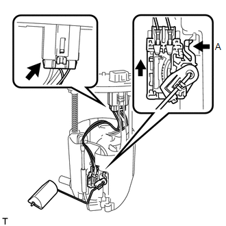
(b) Press down on the fuel sender gauge claw labeled A. Then slide the fuel sender gauge upward.
NOTICE:
Do not touch the sender resistance plate or contact area.
5. REMOVE REAR NO. 2 FLOOR SERVICE HOLE COVER
|
(a) Remove the rear No. 2 floor service hole cover. |
|
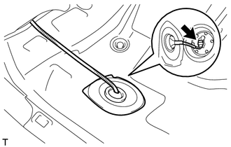
(b) Disconnect the fuel sender gauge connector.
6. REMOVE FUEL SENDER GAUGE ASSEMBLY
|
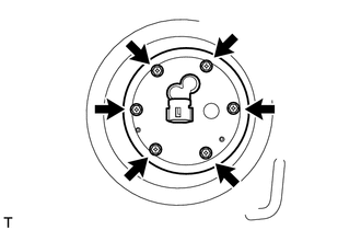
(a) Remove the 6 bolts and fuel sender gauge assembly from the fuel tank. NOTICE: Be careful not to bend the arm of the fuel sender gauge. |
|
Inspection
INSPECTION
PROCEDURE
1. INSPECT FUEL SENDER GAUGE
 Text in Illustration
|
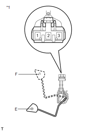
*1 |
Component without harness connected (Fuel Sender Gauge) |
(a) Remove the fuel sender gauge.
(b) Check that the float moves smoothly between F and E.
(c) Measure the resistance between terminals 2 and 1 of the connector according to the value(s) in the table below.
Standard Resistance:
|
Float Level |
Resistance (Ω) |
|---|---|
|
F |
6.5 to 8.5 |
|
Between E and F |
6.5 to 187.2 (Gradually changes) |
|
E |
183.2 to 187.2 |
If the result is not as specified, replace the fuel sender gauge.
2. INSPECT FUEL SENDER GAUGE ASSEMBLY
 Text in Illustration
|
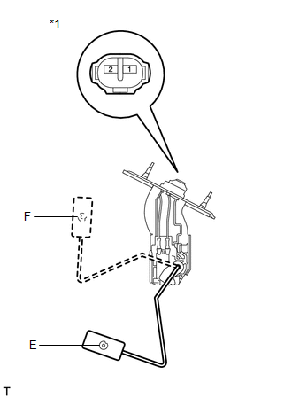
*1 |
Component without connected (Fuel Sender Gauge Assembly) |
(a) Remove the fuel sender gauge assembly.
(b) Check that the float moves smoothly between F and E.
(c) Measure the resistance between terminals 1 and 2 according to the value(s) in the table below.
Standard Resistance:
|
Float Level |
Resistance (Ω) |
|---|---|
|
F |
6.5 to 8.5 |
|
Between E and F |
6.5 to 227.3 (Gradually changes) |
|
E |
222.3 to 227.3 |
If the result is not as specified, replace the fuel sender gauge assembly.
Installation
INSTALLATION
PROCEDURE
1. INSTALL FUEL SENDER GAUGE ASSEMBLY
|
(a) Install the fuel sender gauge assembly to the fuel tank with the 6 bolts. Torque: 3.5 N·m {36 kgf·cm, 31 in·lbf} NOTICE: Be careful not to bend the arm of the fuel sender gauge assembly. |
|
.png)
2. INSTALL REAR NO. 2 FLOOR SERVICE HOLE COVER
|
(a) Connect the fuel sender gauge connector. |
|
.png)
(b) Install the rear No. 2 floor service hole cover with new butyl tape.
3. INSTALL FUEL SENDER GAUGE
|
(a) Install the fuel sender gauge by sliding it downward. NOTICE: Make sure that the fuel sender gauge arm does not bend. |
|
(b) Connect the connector of the fuel sender gauge.
NOTICE:
Do not damage the wire harness.
4. INSTALL FUEL SUCTION TUBE ASSEMBLY WITH PUMP AND GAUGE
(a) Install the fuel suction tube assembly with pump and gauge (See page
.gif) ).
).
5. CONNECT CABLE TO NEGATIVE BATTERY TERMINAL
NOTICE:
When disconnecting the cable, some systems need to be initialized after the cable
is reconnected (See page ).
6. INSPECT FOR FUEL LEAK
 Installation
INSTALLATION
PROCEDURE
1. INSTALL FUEL SUCTION TUBE ASSEMBLY WITH PUMP AND GAUGE
(a) Install a new fuel suction tube set gasket onto the fuel tank.
(b) Connect the fuel tube with the cl ...
 Fuel System
...
Other materials about Toyota Venza:
Wireless Transmitter Memory Function does not Operate
DESCRIPTION
Key IDs can be registered (linked) with either the M1 or M2 seat memory switches.
The key ID registration procedure should be performed while the electrical key transmitter
sub-assembly or door control transmitter assembly is in the vehicle, t ...
High Mounted Stop Light Assembly
Components
COMPONENTS
ILLUSTRATION
Removal
REMOVAL
PROCEDURE
1. REMOVE CENTER STOP LIGHT ASSEMBLY
(a) Using a short screwdriver, remove the 2 screws.
(b) Disconnect the connector and remov ...
Short in Torque Converter Clutch Solenoid Circuit (Shift Solenoid Valve SL)
(P2769,P2770)
DESCRIPTION
Shift solenoid valve SL is turned on and off by signals from the TCM to control
the hydraulic pressure acting on the lock-up relay valve, which then controls operation
of the lock-up clutch.
DTC No.
DTC Detection Conditi ...

0.1244