Toyota Venza: Fuel Injector Circuit
DESCRIPTION
The fuel injector assemblies are located on the intake manifold. They inject fuel into the cylinders based on signals from the ECM.
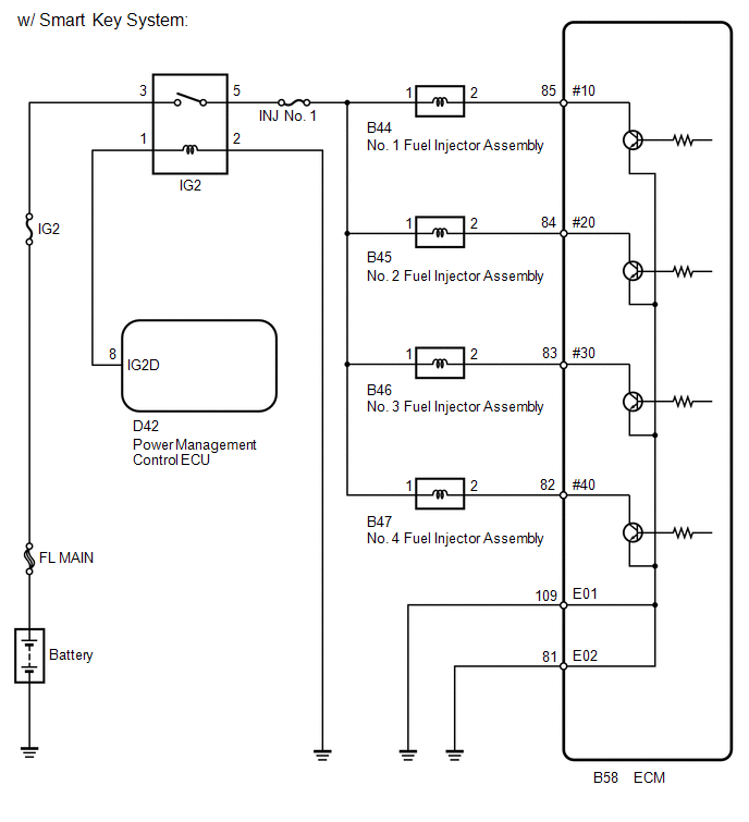
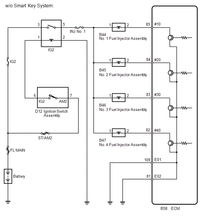
WIRING DIAGRAM
CAUTION / NOTICE / HINT
NOTICE:
Inspect the fuses for circuits related to this system before performing the following inspection procedure.
PROCEDURE
|
1. |
CHECK FUEL INJECTOR ASSEMBLY (POWER SOURCE) |
|
(a) Disconnect the fuel injector assembly connector. |
|
(b) Turn the ignition switch to ON.
(c) Measure the voltage according to the value(s) in the table below.
Standard Voltage:
|
Tester Connection |
Switch Condition |
Specified Condition |
|---|---|---|
|
B44-1 - Body ground |
Ignition switch ON |
11 to 14 V |
|
B45-1 - Body ground |
Ignition switch ON |
11 to 14 V |
|
B46-1 - Body ground |
Ignition switch ON |
11 to 14 V |
|
B47-1 - Body ground |
Ignition switch ON |
11 to 14 V |
|
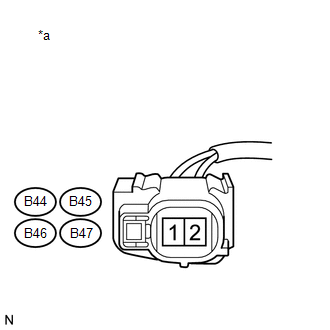
*a |
Front view of wire harness connector (to Fuel Injector Assembly) |
| NG | .gif) |
GO TO STEP 4 |
|
.gif)
|
2. |
INSPECT FUEL INJECTOR ASSEMBLY |
(a) Inspect the fuel injector assembly (See page
.gif) ).
).
HINT:
Perform "Inspection After Repair" after replacing the fuel injector assembly
(See page ).
| NG | |
REPLACE FUEL INJECTOR ASSEMBLY |
|
|
3. |
CHECK HARNESS AND CONNECTOR (FUEL INJECTOR ASSEMBLY - ECM) |
(a) Disconnect the fuel injector assembly connector.
(b) Disconnect the ECM connector.
(c) Measure the resistance according to the value(s) in the table below.
Standard Resistance (Check for Open):
|
Tester Connection |
Condition |
Specified Condition |
|---|---|---|
|
B44-2 - B58-85 (#10) |
Always |
Below 1 Ω |
|
B45-2 - B58-84 (#20) |
Always |
Below 1 Ω |
|
B46-2 - B58-83 (#30) |
Always |
Below 1 Ω |
|
B47-2 - B58-82 (#40) |
Always |
Below 1 Ω |
Standard Resistance (Check for Short):
|
Tester Connection |
Condition |
Specified Condition |
|---|---|---|
|
B44-2 or B58-85 (#10) - Body ground |
Always |
10 kΩ or higher |
|
B45-2 or B58-84 (#20) - Body ground |
Always |
10 kΩ or higher |
|
B46-2 or B58-83 (#30) - Body ground |
Always |
10 kΩ or higher |
|
B47-2 or B58-82 (#40) - Body ground |
Always |
10 kΩ or higher |
| OK | |
PROCEED TO NEXT SUSPECTED AREA SHOWN IN PROBLEM SYMPTOMS TABLE |
| NG | |
REPAIR OR REPLACE HARNESS OR CONNECTOR (FUEL INJECTOR ASSEMBLY - ECM) |
|
4. |
CHECK HARNESS AND CONNECTOR (IG2 RELAY - FUEL INJECTOR ASSEMBLY) |
(a) Disconnect the fuel injector assembly connector.
(b) Remove the IG2 relay from the engine room relay block.
(c) Measure the resistance according to the value(s) in the table below.
Standard Resistance (Check for Open):
|
Tester Connection |
Condition |
Specified Condition |
|---|---|---|
|
B44-1 - 5 (IG2 relay terminal) |
Always |
Below 1 Ω |
|
B45-1 - 5 (IG2 relay terminal) |
Always |
Below 1 Ω |
|
B46-1 - 5 (IG2 relay terminal) |
Always |
Below 1 Ω |
|
B47-1 - 5 (IG2 relay terminal) |
Always |
Below 1 Ω |
Standard Resistance (Check for Short):
|
Tester Connection |
Condition |
Specified Condition |
|---|---|---|
|
B44-1 or 5 (IG2 relay terminal) - Body ground |
Always |
10 kΩ or higher |
|
B45-1 or 5 (IG2 relay terminal) - Body ground |
Always |
10 kΩ or higher |
|
B46-1 or 5 (IG2 relay terminal) - Body ground |
Always |
10 kΩ or higher |
|
B47-1 or 5 (IG2 relay terminal) - Body ground |
Always |
10 kΩ or higher |
| OK | |
CHECK ECM POWER SOURCE CIRCUIT |
| NG | |
REPAIR OR REPLACE HARNESS OR CONNECTOR (IG2 RELAY - FUEL INJECTOR ASSEMBLY) |
 Fuel Pump Control Circuit
DESCRIPTION
1. w/o Smart Key System
When the engine is cranked, the starter relay drive signal output from the ignition
switch is input into the STA terminal of the ECM, and the NE signal generate ...
 ACIS Control Circuit
DESCRIPTION
This circuit opens and closes the Intake Air Control Valve (IACV) in response
to the engine load in order to increase the intake efficiency (ACIS: Acoustic Control
Induction System).
...
Other materials about Toyota Venza:
Diagnosis System
DIAGNOSIS SYSTEM
1. DESCRIPTION
Active torque control 4WD system data can be read in the Data Link Connector
3 (DLC3) of the vehicle. When the system seems to be malfunctioning, use the Techstream
to check for malfunctions and perform repairs. Therefore ...
Inspection
INSPECTION
PROCEDURE
1. INSPECT CYLINDER BLOCK FOR WARPAGE
(a) Using a precision straightedge and feeler gauge, check the surface
that is in contact with the cylinder head gasket for warpage.
Maximum Warpage:
0.05 mm (0.00197 in.)
I ...
TS and CG Terminal Circuit
DESCRIPTION
In the Test Mode (signal check), a malfunction in the speed sensor that cannot
be detected when the vehicle is stopped can be detected while driving.
Transition to the sensor check mode can be performed by connecting terminals
TS and CG of th ...

0.1357