Toyota Venza: Front Stabilizer Bar(for 1ar-fe 2wd)
Components
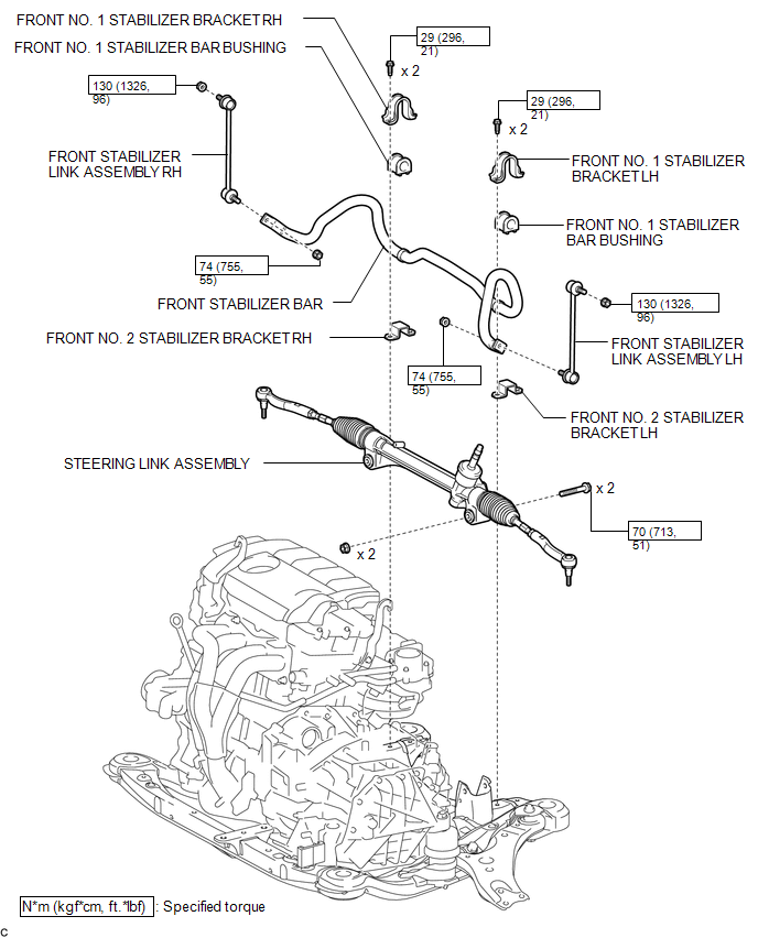
COMPONENTS
ILLUSTRATION
Inspection
INSPECTION
PROCEDURE
1. INSPECT FRONT STABILIZER LINK ASSEMBLY
|
(a) Inspect the turning torque of the ball joint. (1) Secure the front stabilizer link assembly in a vise using aluminum plates. (2) Install the nut to the front stabilizer link assembly stud. (3) Using a torque wrench, turn the nut continuously at a rate of 3 to 5 seconds per turn and take the torque reading on the 5th turn. Turning torque: 0.05 to 1.96 N*m (0.5 to 20 kgf*cm, 0.4 to 17 in.*lbf) If the turning torque is not within the specified range, replace the front stabilizer link assembly with a new one. |
|
.png)
(b) Inspect the dust cover.
(1) Check that the dust cover is not cracked and that there is no grease on it.
Removal
REMOVAL
PROCEDURE
1. REMOVE STEERING LINK ASSEMBLY
HINT:
Refer to the procedure up to Remove Steering Link Assembly (See page
.gif) ).
).
2. REMOVE FRONT STABILIZER LINK ASSEMBLY LH
|
(a) Remove the 2 nuts and front stabilizer link assembly LH. HINT: If the ball joint turns together with the nut, use a hexagon wrench (6 mm) to hold the stud bolt. |
|
.png)
3. REMOVE FRONT STABILIZER LINK ASSEMBLY RH
HINT:
Perform the same procedure as for the LH side.
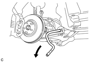
4. REMOVE FRONT STABILIZER BAR WITH BRACKET
|
(a) Remove the front stabilizer bar with bracket from the left side of the vehicle. |
|
5. REMOVE FRONT NO. 1 STABILIZER BRACKET LH
(a) Remove the front No. 1 stabilizer bracket LH from the front No. 1 stabilizer bar bushing.
6. REMOVE FRONT NO. 1 STABILIZER BRACKET RH
HINT:
Perform the same procedure as for the LH side.
7. REMOVE FRONT NO. 2 STABILIZER BRACKET LH
|
(a) Remove the front No. 2 stabilizer bracket LH from the front No. 1 stabilizer bar bushing. |
|
.png)
8. REMOVE FRONT NO. 2 STABILIZER BRACKET RH
HINT:
Perform the same procedure as for the LH side.
9. REMOVE FRONT NO. 1 STABILIZER BAR BUSHING
(a) Remove the 2 front No. 1 stabilizer bar bushings from the front stabilizer bar.
Installation
INSTALLATION
PROCEDURE
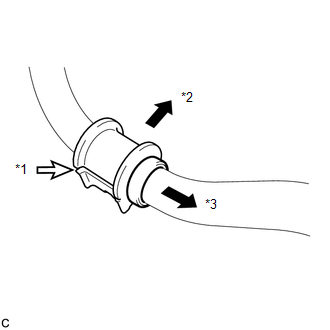
1. INSTALL FRONT NO. 1 STABILIZER BAR BUSHING
|
(a) Install the 2 front No. 1 stabilizer bar bushings to the front stabilizer bar as shown in the illustration. Text in Illustration
NOTICE: When installing the front No. 1 stabilizer bar bushings, make sure that the cutout faces the rear of the vehicle. |
|
2. INSTALL FRONT NO. 2 STABILIZER BRACKET LH
|
(a) Install the front No. 2 stabilizer bracket LH to the front No. 1 stabilizer bar bushing. |
|
.png)
3. INSTALL FRONT NO. 2 STABILIZER BRACKET RH
HINT:
Perform the same procedure as for the LH side.
4. INSTALL FRONT NO. 1 STABILIZER BRACKET LH
(a) Install the front No. 1 stabilizer bracket LH to the front No. 1 stabilizer bar bushing.
5. INSTALL FRONT NO. 1 STABILIZER BRACKET RH
HINT:
Perform the same procedure as for the LH side.
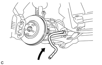
6. INSTALL FRONT STABILIZER BAR WITH BRACKET
|
(a) Install the front stabilizer bar with bracket from the left side of the vehicle. |
|
7. INSTALL FRONT STABILIZER LINK ASSEMBLY LH
|
(a) Install the front stabilizer link assembly LH with the 2 nuts. Torque: Nut A : 130 N·m {1326 kgf·cm, 96 ft·lbf} Nut B : 74 N·m {755 kgf·cm, 55 ft·lbf} HINT: If the ball joint turns together with the nut, use a hexagon wrench (6 mm) to hold the stud bolt. |
|
.png)
8. INSTALL FRONT STABILIZER LINK ASSEMBLY RH
HINT:
Perform the same procedure as for the LH side.
9. INSTALL STEERING LINK ASSEMBLY
HINT:
Refer to the procedure form Install Steering Link Assembly (See page
.gif) ).
).
 Installation
INSTALLATION
PROCEDURE
1. INSTALL FRONT NO. 1 STABILIZER BAR BUSHING
(a) Install the 2 front No. 1 stabilizer bar bushings to the front stabilizer
bar as shown in the illustration.
...
 Front Stabilizer Bar(for 2gr-fe 2wd)
Components
COMPONENTS
ILLUSTRATION
Removal
REMOVAL
PROCEDURE
1. REMOVE FRONT FRAME ASSEMBLY (When Using the Engine Support Bridge)
(See page )
2. REMOVE ENGINE ASSEMBLY WITH TRANSAXLE ( ...
Other materials about Toyota Venza:
How To Proceed With Troubleshooting
CAUTION / NOTICE / HINT
HINT:
Use the following procedure listed to troubleshoot the Active Torque
Control 4WD system.
*: Use the Techstream.
PROCEDURE
1.
VEHICLE BROUGHT TO WORKSHOP
...
Reassembly
REASSEMBLY
PROCEDURE
1. INSTALL NO. 2 STEERING RACK BOOT
(a) Apply lithium soap base glycol grease to the inside of the small
opening of a new No. 2 steering rack boot.
(b) Install the No. 2 ste ...
Disassembly
DISASSEMBLY
PROCEDURE
1. REMOVE NO. 2 ANTENNA CORD SUB-ASSEMBLY (w/o Sliding Roof)
2. REMOVE NO. 2 ANTENNA CORD SUB-ASSEMBLY (w/ Sliding Roof)
3. REMOVE VANITY LIGHT ASSEMBLY
(a) Remove the vanity light assembly (See page
).
HINT:
Use the same p ...

0.1397