Toyota Venza: Front Seat Inner Belt Assembly
Components
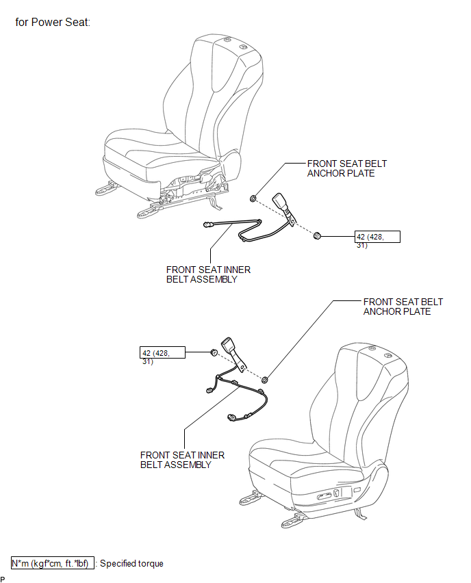
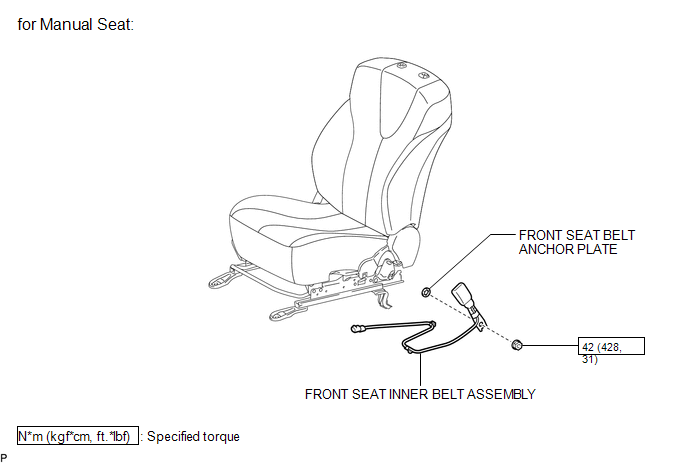
COMPONENTS
ILLUSTRATION
ILLUSTRATION
Inspection
INSPECTION
PROCEDURE
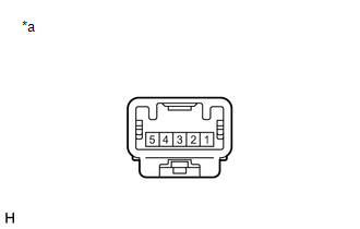
1. INSPECT FRONT SEAT INNER BELT ASSEMBLY LH (w/ Seat Position Memory System)
|
(a) Measure the resistance according to the value(s) in the table below. Standard Resistance:
If the result is not as specified, replace the front seat inner belt assembly LH. |
|
Removal
REMOVAL
PROCEDURE
1. REMOVE FRONT SEAT ASSEMBLY (for Manual Seat)
(See page .gif) )
)
2. REMOVE FRONT SEAT ASSEMBLY (for Power Seat)
(See page )
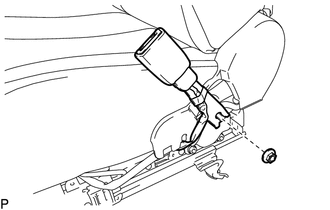
3. REMOVE FRONT SEAT INNER BELT ASSEMBLY (for Manual Seat)
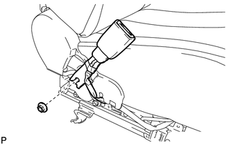
(a) Disconnect the connector and disengage each clamp.
|
(b) Remove the nut and front seat inner belt assembly. |
|
4. REMOVE FRONT SEAT INNER BELT ASSEMBLY (for Power Seat)
(a) Disconnect each connector and disengage each clamp.
|
(b) Remove the nut and front seat inner belt assembly. |
|
5. REMOVE FRONT SEAT BELT ANCHOR PLATE
(a) Remove the front seat belt anchor plate.
Installation
INSTALLATION
PROCEDURE
1. INSTALL FRONT SEAT BELT ANCHOR PLATE
(a) Install the front seat belt anchor plate.
2. INSTALL FRONT SEAT INNER BELT ASSEMBLY (for Manual Seat)
|
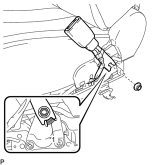
(a) Install the front seat inner belt assembly with the nut. Text in Illustration
Torque: 42 N·m {428 kgf·cm, 31 ft·lbf} NOTICE: Do not allow the anchor part of the front seat inner belt assembly to overlap the protruding part of the front seat adjuster. |
|
(b) Connect the connector and engage each clamp.
3. INSTALL FRONT SEAT INNER BELT ASSEMBLY (for Power Seat)
|
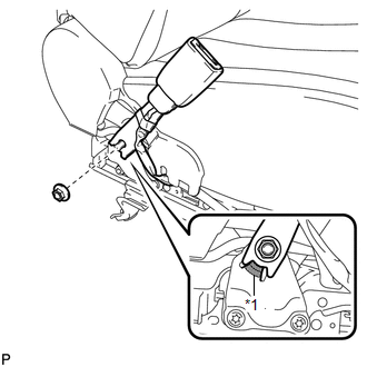
(a) Install the front seat inner belt assembly with the nut. Text in Illustration
Torque: 42 N·m {428 kgf·cm, 31 ft·lbf} NOTICE: Do not allow the anchor part of the front seat inner belt assembly to overlap the protruding part of the front seat adjuster. |
|
(b) Connect each connector and engage each clamp.
4. INSTALL FRONT SEAT ASSEMBLY (for Manual Seat)
(See page .gif) )
)
5. INSTALL FRONT SEAT ASSEMBLY (for Power Seat)
(See page )
 Front Passenger Seat Belt Warning Light
Components
COMPONENTS
ILLUSTRATION
Installation
INSTALLATION
PROCEDURE
1. INSTALL ACCESSORY METER ASSEMBLY (w/o Rear View Monitor System)
(a) Connect the connector.
(b) Engage the 2 clam ...

Other materials about Toyota Venza:
Precaution
PRECAUTION
1. PRECAUTION FOR DISCONNECTING CABLE FROM NEGATIVE BATTERY TERMINAL
NOTICE:
When disconnecting the cable from the negative (-) battery terminal, initialize
the following system after the cable is reconnected.
System Name
...
Adjustment
ADJUSTMENT
CAUTION / NOTICE / HINT
HINT:
Centering bolts are used to mount the hood hinge and hood lock. The
hood and hood lock cannot be adjusted with the centering bolts installed.
Substitute the centering bolts with standard bolts when ...
Door Side Airbag Sensor RH Malfunction (B1690/15)
DESCRIPTION
The side collision sensor RH circuit (to determine deployment of the front seat
side airbag assembly RH and curtain shield airbag assembly RH) is composed of the
center airbag sensor assembly, rear airbag sensor RH and side airbag sensor RH.
...

0.1574