Toyota Venza: Front Power Seat does not Operate with Front Power Seat Switch
DESCRIPTION
Signals are input into the position control ECU and switch assembly. The built-in ECU manages the signals received from the position control ECU and switch assembly, and operates each motor. If the position control ECU and switch assembly receives more than 2 motor operation signals, the motor is stopped. Manual operation is restarted after the position control ECU and switch assembly receives 1 signal only.
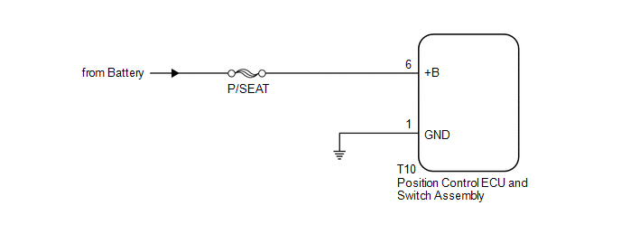
WIRING DIAGRAM
CAUTION / NOTICE / HINT
NOTICE:
Inspect the fuses for circuits related to this system before performing the following inspection procedure.
PROCEDURE
|
1. |
CHECK FRONT POWER SEAT OPERATION |
(a) Check that each function of the power seat operates normally by using the
position control ECU and switch assembly (See page
.gif) ).
).
|
Result |
Proceed to |
|---|---|
|
All power seat functions do not operate |
A |
|
One or more power seat functions do not operate |
B |
| B | .gif) |
GO TO OTHER DIAGNOSIS PROCEDURE (One or more Power Seat Motors do not Operate) |
|
.gif)
|
2. |
CHECK HARNESS AND CONNECTOR (POSITION CONTROL ECU AND SWITCH ASSEMBLY - BATTERY) |
(a) Disconnect the T10 position control ECU and switch assembly connectors.
(b) Measure the voltage according to the value(s) in the table below.
Standard Voltage:
|
Tester Connection |
Condition |
Specified Condition |
|---|---|---|
|
T10-6 (+B) - Body ground |
Always |
11 to 14 V |
| NG | |
REPAIR OR REPLACE HARNESS OR CONNECTOR |
|
|
3. |
CHECK HARNESS AND CONNECTOR (POSITION CONTROL ECU AND SWITCH ASSEMBLY - BODY GROUND) |
(a) Measure the resistance according to the value(s) in the table below.
Standard Resistance:
|
Tester Connection |
Condition |
Specified Condition |
|---|---|---|
|
T10-1 (GND) - Body ground |
Always |
Below 1 Ω |
| OK | |
REPLACE POSITION CONTROL ECU AND SWITCH ASSEMBLY |
| NG | |
REPAIR OR REPLACE HARNESS OR CONNECTOR |
 Short in Sensor with Motor Power Supply Circuit (B2658)
DESCRIPTION
This DTC is stored if sensor voltage does not reach the designated voltage while
the slide motor is operating.
DTC Code
DTC Detection Condition
Trouble ...
 One or more Power Seat Motors do not Operate
DESCRIPTION
Signals are input into the position control ECU and switch assembly. The built-in
ECU manages the signals received from the position control ECU and switch assembly,
and operates each ...
Other materials about Toyota Venza:
Atf Temperature Sensor(when Using The Engine Support Bridge)
Components
COMPONENTS
ILLUSTRATION
Inspection
INSPECTION
PROCEDURE
1. INSPECT ATF TEMPERATURE SENSOR ASSEMBLY
(a) Measure the resistance according to the value(s) in the table below.
Standard Resistance:
Tester C ...
Reassembly
REASSEMBLY
PROCEDURE
1. INSTALL FRONT SEAT WIRE
(a) Engage the 2 clamps to install the front seat wire.
(b) Connect the 4 connectors.
2. INSTALL OCCUPANT CLASSIFICATION ECU
3. INSTALL FRONT LOW ...
System Diagram
SYSTEM DIAGRAM
1. AUTOMATIC LIGHT CONTROL SYSTEM
2. LIGHT AUTO TURN-OFF SYSTEM
Communication Table
Transmitter
Receiver
Line
Data Name
Certification ECU (Smart Key ECU Assembly)
Mai ...

0.1417