Toyota Venza: Front Passenger Side Door ECU Communication Stop (B2322)
DESCRIPTION
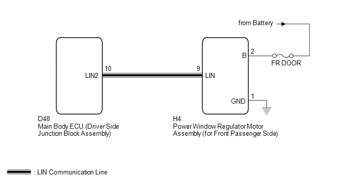
This DTC is stored when LIN communication between the power window regulator motor assembly (for front passenger side) and main body ECU (driver side junction block assembly) stops for more than 10 seconds.
|
DTC No. |
DTC Detection Condition |
Trouble Area |
|---|---|---|
|
B2322 |
No communication between the power window regulator motor assembly (for front passenger side) and main body ECU (driver side junction block assembly) for more than 10 seconds. |
|
WIRING DIAGRAM
CAUTION / NOTICE / HINT
NOTICE:
- When the power window regulator motor assembly (for front passenger
side) is replaced or removed and reinstalled, it requires initialization
(See page
.gif) ).
). - When using the Techstream to troubleshoot with the ignition switch off:
Connect the Techstream to the DLC3, and turn the courtesy switch on and off at 1.5-second intervals until communication between the Techstream and vehicle begins.
PROCEDURE
|
1. |
CHECK HARNESS AND CONNECTOR (POWER WINDOW REGULATOR MOTOR - BATTERY AND BODY GROUND) |
|
(a) Disconnect the H4 motor connector. |
|
(b) Measure the resistance and voltage according to the value(s) in the table below.
Standard Resistance:
|
Tester Connection |
Condition |
Specified Condition |
|---|---|---|
|
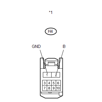
H4-1 (GND) - Body ground |
Always |
Below 1 Ω |
Standard Voltage:
|
Tester Connection |
Condition |
Specified Condition |
|---|---|---|
|
H4-2 (B) - Body ground |
Always |
11 to 14 V |
|
*1 |
Front view of wire harness connector (to Power Window Regulator Motor Assembly (for Front Passenger Side)) |
| NG | .gif) |
REPAIR OR REPLACE HARNESS OR CONNECTOR |
|
.gif)
|
2. |
CHECK HARNESS AND CONNECTOR (MAIN BODY ECU - POWER WINDOW REGULATOR MOTOR ASSEMBLY) |
|
(a) Disconnect the D48 ECU connector. |
|
(b) Measure the resistance according to the value(s) in the table below.
Standard Resistance:
|
Tester Connection |
Condition |
Specified Condition |
|---|---|---|
|
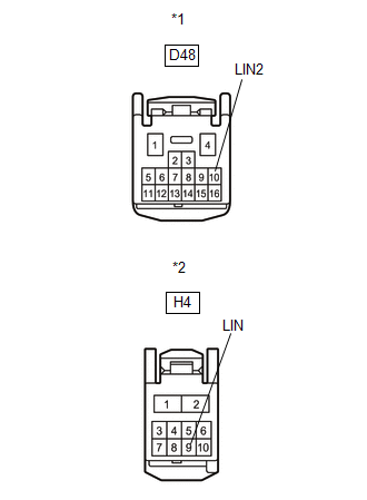
D48-10 (LIN2) - H4-9 (LIN) |
Always |
Below 1 Ω |
|
D48-10 (LIN2) - Body ground |
Always |
10 kΩ or higher |
|
*1 |
Front view of wire harness connector (to Main Body ECU (Driver Side Junction Block Assembly)) |
|
*2 |
Front view of wire harness connector (to Power Window Regulator Motor Assembly (for Front Passenger Side)) |
| NG | |
REPAIR OR REPLACE HARNESS OR CONNECTOR |
|
|
3. |
REPLACE POWER WINDOW REGULATOR MOTOR ASSEMBLY (for FRONT PASSENGER SIDE) |
(a) Replace the power window regulator motor assembly (for front passenger side)
(See page ).
|
|
4. |
CHECK DTC OUTPUT |
(a) Clear the DTC (See page ).
(b) Recheck for DTCs.
OK:
DTC B2322 is not output.
| OK | |
END (POWER WINDOW REGULATOR MOTOR ASSEMBLY WAS DEFECTIVE) |
| NG | |
REPLACE MAIN BODY ECU (DRIVER SIDE JUNCTION BLOCK ASSEMBLY) |
 LIN Communication Bus Malfunction (B2325)
DESCRIPTION
The main body ECU (driver side junction block assembly) monitors communication
between all the ECUs connected to the door bus lines. When the main body ECU (driver
side junction block ...
 Rear Door RH ECU Communication Stop (B2323)
DESCRIPTION
This DTC is stored when LIN communication between the power window regulator
motor assembly (for rear RH side) and main body ECU (driver side junction block
assembly) stops for more t ...
Other materials about Toyota Venza:
Inspection
INSPECTION
PROCEDURE
1. INSPECT BRAKE DISC INSIDE DIAMETER
(a) Using a brake drum gauge or an equivalent tool, measure the inside
diameter of the disc.
Standard inside diameter of a new disc:
190 mm (7.48 in.)
Maximum inside diamete ...
Actuator Supply Voltage Circuit / Open (P0657)
MONITOR DESCRIPTION
The ECM monitors the output voltage to the throttle actuator. This self-check
ensures that the ECM is functioning properly. The output voltage is usually 0 V
when the ignition switch is turned off. If the output voltage is higher than ...
Removal
REMOVAL
PROCEDURE
1. REMOVE REAR SEAT HEADREST ASSEMBLY
(a) Press the headrest support button and pull up the rear seat headrest
assembly as shown in the illustration.
2. REMOVE REAR SEAT CENTER ...

0.1261