Toyota Venza: Front Door Courtesy Switch
Components
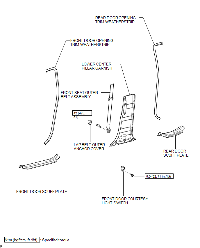
COMPONENTS
ILLUSTRATION
Inspection
INSPECTION
PROCEDURE
1. INSPECT COURTESY LIGHT SWITCH
(a) Measure the resistance according to the value(s) in the table below.
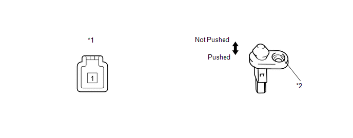
Standard Resistance:
|
Tester Connection |
Switch Condition |
Specified Condition |
|---|---|---|
|
1 - Switch body |
Pushed |
10 kΩ or higher |
|
1 - Switch body |
Not pushed |
Below 1 Ω |
|
*1 |
Component without harness connected (Courtesy Light Switch) |
*2 |
Switch Body |
If the result is not as specified, replace the courtesy light switch.
Removal
REMOVAL
PROCEDURE
1. REMOVE FRONT DOOR SCUFF PLATE
.gif)
2. DISCONNECT FRONT DOOR OPENING TRIM WEATHERSTRIP
3. REMOVE REAR DOOR SCUFF PLATE
4. DISCONNECT REAR DOOR OPENING TRIM WEATHERSTRIP
5. REMOVE LAP BELT OUTER ANCHOR COVER
6. DISCONNECT FRONT SEAT OUTER BELT ASSEMBLY
7. REMOVE LOWER CENTER PILLAR GARNISH
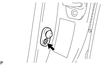
8. REMOVE FRONT DOOR COURTESY LIGHT SWITCH
(a) Disconnect the connector.
|
(b) Using "TORX" socket wrench T30, remove the "TORX" bolt and front door courtesy light switch. |
|
Installation
INSTALLATION
PROCEDURE
1. INSTALL FRONT DOOR COURTESY LIGHT SWITCH
|
(a) Using "TORX" socket wrench T30, install the front door courtesy light switch with the "TORX" bolt. Torque: 8.0 N·m {82 kgf·cm, 71 in·lbf} |
|
.png)
(b) Connect the connector.
2. INSTALL LOWER CENTER PILLAR GARNISH
.gif)
3. CONNECT FRONT SEAT OUTER BELT ASSEMBLY
4. INSTALL LAP BELT OUTER ANCHOR COVER
5. CONNECT REAR DOOR OPENING TRIM WEATHERSTRIP
6. INSTALL REAR DOOR SCUFF PLATE
7. CONNECT FRONT DOOR OPENING TRIM WEATHERSTRIP
8. INSTALL FRONT DOOR SCUFF PLATE
 Door Courtesy Light
Components
COMPONENTS
ILLUSTRATION
Removal
REMOVAL
PROCEDURE
1. REMOVE COURTESY LIGHT ASSEMBLY
(a) Using a screwdriver wrapped with protective tape, disengage the claw.
Text ...
 Glove Box Light
Components
COMPONENTS
ILLUSTRATION
Inspection
INSPECTION
PROCEDURE
1. INSPECT GLOVE BOX LIGHT ASSEMBLY
(a) Connect a positive (+) lead from the battery to terminal 1 and a
...
Other materials about Toyota Venza:
Installation
INSTALLATION
CAUTION / NOTICE / HINT
NOTICE:
When disconnecting the steering intermediate shaft assembly and pinion shaft
of the steering gear assembly, be sure to place matchmarks before servicing.
PROCEDURE
1. INSTALL TIE ROD ASSEMBLY LH
( ...
Door Unlock Detection Switch Circuit
DESCRIPTION
The main body ECU (driver side junction block assembly) detects the condition
of the door unlock detection switch.
WIRING DIAGRAM
PROCEDURE
1.
READ VALUE USING TECHSTREAM
(a) Connect the Techstream to the DL ...
AVC-LAN Circuit
DESCRIPTION
Each unit of the navigation system connected to the AVC-LAN (communication bus)
transmits switch signals via AVC-LAN communication.
If a short to +B or short to ground occurs in the AVC-LAN, the navigation system
will not function normally be ...

0.1749