Toyota Venza: Front Brake Flexible Hose
Components
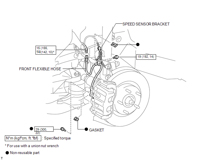
COMPONENTS
ILLUSTRATION
Installation
INSTALLATION
CAUTION / NOTICE / HINT
NOTICE:
- Because the left and right hoses are not interchangeable, verify the part number when installing the flexible hoses.
- If the hoses are to be reused, connect them after checking the identification marks placed when each hose was disconnected.
PROCEDURE
1. INSTALL FRONT FLEXIBLE HOSE
|
(a) Connect the front flexible hose to the disc brake cylinder assembly with a new union bolt and a new gasket. Torque: 29 N·m {300 kgf·cm, 22 ft·lbf} HINT: Install the front flexible hose lock securely into the lock hole in the front disc brake cylinder assembly. |
|
.png)
|
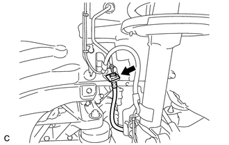
(b) Install the front flexible hose with a new clip. NOTICE: Install the clip as far as it will go. |
|
|
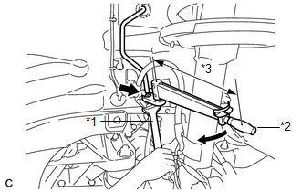
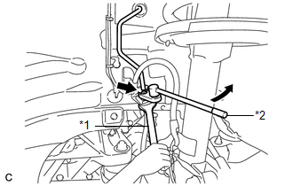
(c) Using a union nut wrench, connect the brake line to the front flexible hose while holding the front flexible hose with a wrench. Text in Illustration
Torque: Specified Tightening Torque : 15 N·m {155 kgf·cm, 11 ft·lbf} NOTICE:
HINT:
|
|
|
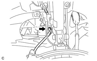
(d) Install the front flexible hose together with the speed sensor bracket to the absorber bracket with the bolt. Torque: 19 N·m {192 kgf·cm, 14 ft·lbf} NOTICE: First install the speed sensor harness bracket, and then install the flexible hose bracket. |
|
2. FILL RESERVOIR WITH BRAKE FLUID
.gif)
3. BLEED BRAKE LINE
4. INSPECT FOR BRAKE FLUID LEAK
5. INSPECT FLUID LEVEL IN RESERVOIR
6. INSTALL FRONT WHEEL
Torque:
103 N·m {1050 kgf·cm, 76 ft·lbf}
Removal
REMOVAL
CAUTION / NOTICE / HINT
NOTICE:
If both the left and right side hoses are removed at the same time, be sure to place identification marks indicating the position on each side.
HINT:
- Use the same procedure for the LH side and RH side.
- The following procedure listed is for the LH side.
PROCEDURE
1. REMOVE FRONT WHEEL
2. DRAIN BRAKE FLUID
NOTICE:
If brake fluid leaks onto any painted surface, immediately wash it off.
3. REMOVE FRONT FLEXIBLE HOSE
|
(a) Remove the union bolt and gasket, and separate the front flexible hose. |
|
.png)
|
(b) Using a union nut wrench, disconnect the brake line from the front flexible hose while holding the front flexible hose with a wrench. Text in Illustration
NOTICE:
|
|
|
(c) Remove the clip. |
|
.png)
|
(d) Remove the bolt and front flexible hose from the absorber bracket. |
|
.png)
 Installation
INSTALLATION
PROCEDURE
1. TEMPORARILY TIGHTEN FRONT DISC BRAKE BLEEDER PLUG
(a) Temporarily tighten the front disc brake bleeder plug.
HINT:
Fully tighten the front disc brake bleeder plug after ...
 Brake (rear)
...
Other materials about Toyota Venza:
Reassembly
REASSEMBLY
PROCEDURE
1. INSTALL NO. 2 STEERING RACK BOOT
(a) Apply lithium soap base glycol grease to the inside of the small
opening of a new No. 2 steering rack boot.
(b) Install the No. 2 ste ...
Installation
INSTALLATION
CAUTION / NOTICE / HINT
HINT:
Use the same procedure for the LH side and RH side.
The following procedure listed below is for the LH side.
PROCEDURE
1. SECURE FRONT SHOCK ABSORBER ASSEMBLY
(a) Install the bolt an ...
Removal
REMOVAL
PROCEDURE
1. RECOVER REFRIGERANT FROM REFRIGERATION SYSTEM
2. DISCONNECT CABLE FROM NEGATIVE BATTERY TERMINAL
NOTICE:
When disconnecting the cable, some systems need to be initialized after the cable
is reconnected (See page ).
3. REMOVE FR ...

0.13