Toyota Venza: Front Blower Motor
Components
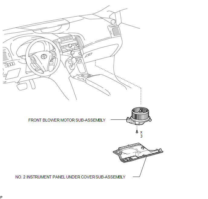
COMPONENTS
ILLUSTRATION
Installation
INSTALLATION
PROCEDURE
1. INSTALL FRONT BLOWER MOTOR SUB-ASSEMBLY
|
(a) Install the front blower motor sub-assembly with the 3 screws. |
|
(b) Connect the connector.
2. INSTALL NO. 2 INSTRUMENT PANEL UNDER COVER SUB-ASSEMBLY
.gif)
3. CONNECT CABLE TO NEGATIVE BATTERY TERMINAL
NOTICE:
When disconnecting the cable, some systems need to be initialized after the cable
is reconnected (See page ).
Removal
REMOVAL
PROCEDURE
1. DISCONNECT CABLE FROM NEGATIVE BATTERY TERMINAL
NOTICE:
When disconnecting the cable, some systems need to be initialized after the cable
is reconnected (See page .gif) ).
).
2. REMOVE NO. 2 INSTRUMENT PANEL UNDER COVER SUB-ASSEMBLY
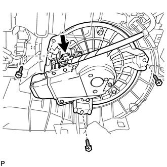
3. REMOVE FRONT BLOWER MOTOR SUB-ASSEMBLY
|
(a) Disconnect the connector. |
|
.png)
(b) Remove the 3 screws and front blower motor sub-assembly.
 Reassembly
REASSEMBLY
PROCEDURE
1. INSTALL COOLER DRYER
(a) Using pliers, install a new cooler dryer to the modulator.
(b) Apply sufficien ...

Other materials about Toyota Venza:
Problem Symptoms Table
PROBLEM SYMPTOMS TABLE
HINT:
Use the table below to help determine the cause of problem symptoms.
If multiple suspected areas are listed, the potential causes of the symptoms
are listed in order of probability in the "Suspected Area" ...
On-vehicle Inspection
ON-VEHICLE INSPECTION
CAUTION / NOTICE / HINT
HINT:
Use the same procedure for the RH side and LH side.
The procedure listed below is for the LH side.
PROCEDURE
1. REMOVE REAR WHEEL
2. SEPARATE REAR DISC BRAKE CALIPER ASSEMBLY
3. RE ...
Route cannot be Calculated
PROCEDURE
1.
SET DESTINATION
(a) Set another destination and check if the system can calculate the route correctly.
OK:
Route can be correctly calculated.
OK
END
NG
PROCEED T ...

0.1371