Toyota Venza: Engine Coolant Temperature Receiver Gauge Malfunction
DESCRIPTION
In this circuit, the meter CPU receives engine coolant temperature signals from the ECM using the CAN communication system (CAN No. 1 Bus). The meter CPU displays engine coolant temperature that is calculated based on the data received from the ECM.
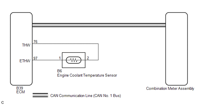
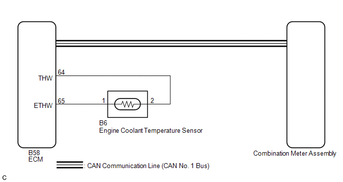
WIRING DIAGRAM
1. for 2GR-FE
2. for 1AR-FE
CAUTION / NOTICE / HINT
HINT:
If there is an open or short in the engine coolant temperature sensor circuit,
the ECM stores the DTCs. Refer to troubleshoot SFI System (See page
.gif) for 2GR-FE,
for 1AR-FE).
for 2GR-FE,
for 1AR-FE).
PROCEDURE
|
1. |
CHECK CAN COMMUNICATION SYSTEM |
(a) Check if a CAN communication DTC is output (See page
).
|
Result |
Proceed to |
|---|---|
|
CAN communication DTC is not output. |
A |
|
CAN communication DTC is output. |
B |
| B | .gif) |
GO TO CAN COMMUNICATION SYSTEM |
|
.gif)
|
2. |
PERFORM ACTIVE TEST USING TECHSTREAM (WATER TEMPERATURE METER OPERATION) |
(a) Connect the Techstream to the DLC3.
(b) Turn the ignition switch to ON.
(c) Turn the Techstream on.
(d) Enter the following menus: Body Electrical / Combination Meter / Active Test.
(e) Check the operation by referring to the table below.
Combination Meter|
Tester Display |
Test Part |
Control Range |
Diagnostic Note |
|---|---|---|---|
|
Water Temperature Meter Operation |
Engine coolant temperature receiver gauge |
Low, Normal, High |
Confirm that the vehicle is stopped with the engine idling |
OK:
Engine coolant temperature receiver gauge indication is normal.
| NG | |
REPLACE COMBINATION METER ASSEMBLY |
|
|
3. |
READ VALUE USING TECHSTREAM (COOLANT TEMPERATURE) |
(a) Connect the Techstream to the DLC3.
(b) Turn the ignition switch to ON.
(c) Turn the Techstream on.
(d) Enter the following menus: Body Electrical / Combination Meter / Data List.
(e) Check the values by referring to the table below.
Combination Meter|
Tester Display |
Measurement Item/Range |
Normal Condition |
Diagnostic Note |
|---|---|---|---|
|
Coolant Temperature |
Engine coolant temperature/Min.: 0°C (32°F), Max.: 127.5°C (261.5°F) |
After warming up: 80 to 100°C (176 to 212°F) |
|
OK:
Engine coolant temperature value displayed on the Techstream is almost the same as engine coolant temperature receiver gauge indication.
| NG | |
REPLACE COMBINATION METER ASSEMBLY |
|
|
4. |
READ VALUE USING TECHSTREAM (COOLANT TEMP) |
(a) Connect the Techstream to the DLC3.
(b) Turn the ignition switch to ON.
(c) Turn the Techstream on.
(d) Enter the following menus: Powertrain / Engine and ECT / Data List.
(e) Check the values by referring to the table below.
Engine and ECT (for 2GR-FE)|
Tester Display |
Measurement Item/Range |
Normal Condition |
Diagnostic Note |
|---|---|---|---|
|
Engine Speed |
Vehicle speed/Min.: 0 rpm, Max.: 16383 rpm |
600 to 700 rpm (When idling) |
- |
|
Coolant Temp |
Engine coolant temperature/Min.: -40°C (-40°F), Max: 215°C (419°F) |
80 to 100°C (176 to 212°F): After warming up |
|
|
Tester Display |
Measurement Item/Range |
Normal Condition |
Diagnostic Note |
|---|---|---|---|
|
Engine Speed |
Vehicle speed/Min.: 0 rpm, Max.: 16383 rpm |
600 to 700 rpm (When idling) |
- |
|
Coolant Temp |
Engine coolant temperature/Min.: -40°C (-40°F), Max: 140°C (284°F) |
80 to 100°C (176 to 212°F): After warming up |
|
OK:
Engine coolant temperature value displayed on the Techstream is almost the same as the Techstream indication (Body Electrical / Combination Meter / Data List).
|
Result |
Proceed to |
|---|---|
|
OK |
A |
|
NG (for 2GR-FE) |
B |
|
NG (for 1AR-FE) |
C |
| A | |
REPLACE COMBINATION METER ASSEMBLY |
| B | |
REPLACE ECM (for 2GR-FE) |
| C | |
REPLACE ECM (for 1AR-FE) |
 Tachometer Malfunction
DESCRIPTION
In this circuit, the meter CPU receives engine speed signals from the ECM using
the CAN communication system (CAN No. 1 Bus). The meter CPU displays the engine
speed calculated based ...
 Fuel Receiver Gauge Malfunction
DESCRIPTION
The meter CPU uses the fuel sender gauge assembly to determine the level
of the fuel in the fuel tank. The resistance of the fuel sender gauge will
vary between approximate ...
Other materials about Toyota Venza:
Removal
REMOVAL
PROCEDURE
1. REMOVE FRONT DOOR SCUFF PLATE LH
(a) Disengage the 3 clips, 7 claws and guide, and remove the front door
scuff plate LH.
2. REMOVE COWL SIDE TRIM SUB-ASSEMBLY LH
...
ECU Power Source Circuit
DESCRIPTION
This circuit provides power for main body ECU (driver side junction block assembly)
operation.
WIRING DIAGRAM
PROCEDURE
1.
CHECK DRIVER SIDE JUNCTION BLOCK ASSEMBLY (MAIN BODY ECU (POWER SOURCE))
...
Installation
INSTALLATION
PROCEDURE
1. INSTALL REAR DOOR UPPER WINDOW FRAME MOULDING
(a) Engage the guide and install the rear door upper window frame moulding
to the door frame.
(b) Using an air riveter or ...

0.1485