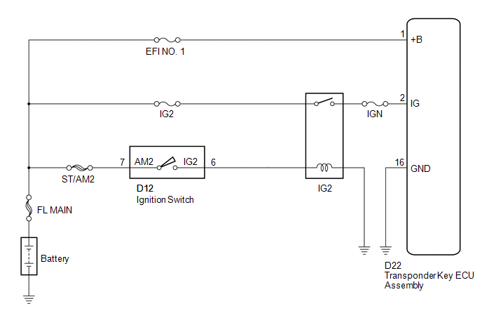
Toyota Venza: ECU Power Source Circuit
DESCRIPTION
This circuit provides power to operate the transponder key ECU assembly.
WIRING DIAGRAM
CAUTION / NOTICE / HINT
NOTICE:
If the transponder key ECU assembly is replaced, register the key and ECU communication
ID (See page .gif) ).
).
PROCEDURE
|
1. |
CHECK HARNESS AND CONNECTOR (TRANSPONDER KEY ECU - BATTERY AND BODY GROUND) |
|
(a) Disconnect the transponder key ECU assembly connector. |
|
(b) Measure the voltage and resistance according to the value(s) in the table below.
Standard Voltage:
|
Tester Connection |
Condition |
Specified Condition |
|---|---|---|
|
D22-1 (+B) - Body ground |
Always |
11 to 14 V |
|
D22-2 (IG) - Body ground |
Ignition switch off |
Below 1 V |
|
D22-2 (IG) - Body ground |
Ignition switch ON |
11 to 14 V |
Standard Resistance:
|
Tester Connection |
Condition |
Specified Condition |
|---|---|---|
|
D22-16 (GND) - Body ground |
Always |
Below 1 Ω |
|
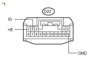
*1 |
Front view of wire harness connector (to Transponder Key ECU Assembly) |
| OK | .gif) |
PROCEED TO NEXT SUSPECTED AREA SHOWN IN PROBLEM SYMPTOMS TABLE |
| NG | |
REPAIR OR REPLACE HARNESS OR CONNECTOR, OR REPLACE FUSE |
 Security Indicator Light Circuit
DESCRIPTION
The security indicator light blinks continuously due to a continuous signal received
from the transponder key ECU assembly while in the armed state.
WIRING DIAGRAM
CAUTION / NOTICE ...
 Diagnosis Circuit
DESCRIPTION
This circuit is used to read the DTCs that are output from the transponder key
ECU assembly with the Techstream.
WIRING DIAGRAM
CAUTION / NOTICE / HINT
NOTICE:
If the transponder ...
Other materials about Toyota Venza:
Diagnostic Trouble Code Chart
DIAGNOSTIC TROUBLE CODE CHART
Audio and Visual System
DTC Code
Detection Item
See page
B1532
LVDS Signal Malfunction (from Extension Module)
B1551
HD Radio ...
How To Proceed With Troubleshooting
CAUTION / NOTICE / HINT
HINT:
*: Use the Techstream.
PROCEDURE
1.
VEHICLE BROUGHT TO WORKSHOP
NEXT
2.
CUSTOMER PROBLEM ANALYSIS
...
Height Control Sensor Malfunction (B2416)
DESCRIPTION
The DTC is stored when the headlight leveling ECU assembly detects malfunctions
in the rear height control sensor sub-assembly RH power source or rear height control
sensor sub-assembly RH.
DTC No.
DTC Detecting Conditio ...

0.151