Toyota Venza: ECU Power Source Circuit
DESCRIPTION
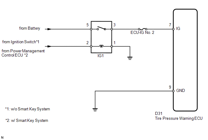
This is the power source for the tire pressure warning ECU.
WIRING DIAGRAM
CAUTION / NOTICE / HINT
NOTICE:
- When replacing the tire pressure warning ECU, read the transmitter IDs stored in the old ECU using the Techstream and write them down before removal.
- It is necessary to perform registration (See page
.gif) ) of the transmitter IDs into the tire
) of the transmitter IDs into the tire
pressure warning ECU after the ECU has been replaced.
PROCEDURE
|
1. |
INSPECT FUSE (ECU-IG NO. 2) |
(a) Remove the ECU-IG No. 2 fuse from the driver side junction block.
(b) Measure the resistance according to the value(s) in the table below.
Standard Resistance:
|
Tester Connection |
Condition |
Specified Condition |
|---|---|---|
|
ECU-IG No. 2 fuse |
Always |
Below 1 Ω |
| NG | .gif) |
REPLACE FUSE |
|
.gif)
|
2. |
INSPECT IGNITION RELAY NO. 1 |
|
(a) Remove the IG1 relay from the driver side junction block. |
|
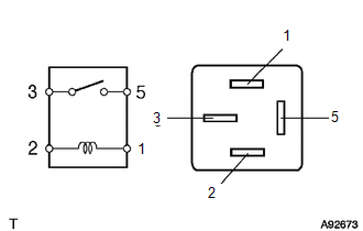
(b) Measure the resistance according to the value(s) in the table below.
Standard Resistance:
|
Tester Connection |
Condition |
Specified Condition |
|---|---|---|
|
3 - 5 |
Battery voltage is not applied between terminals 1 and 2 |
10 kΩ or higher |
|
Battery voltage is applied between terminals 1 and 2 |
Below 1 Ω |
| NG | |
REPLACE IGNITION RELAY NO. 1 |
|
|
3. |
CHECK HARNESS AND CONNECTOR (ECU - BATTERY AND BODY GROUND) |
|
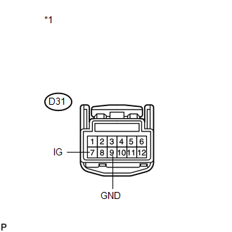
(a) Disconnect the D31 ECU connector. |
|
(b) Measure the voltage according to the value(s) in the table below.
Standard Voltage:
|
Tester Connection |
Switch Condition |
Specified Condition |
|---|---|---|
|
D31-7 (IG) - Body ground |
Ignition switch ON |
11 to 14 V |
|
Ignition switch off |
Below 1 V |
|
*1 |
Front view of wire harness connector (to Tire Pressure Warning ECU) |
(c) Measure the resistance according to the value(s) in the table below.
Standard Resistance:
|
Tester Connection |
Condition |
Specified Condition |
|---|---|---|
|
D31-9 (GND) - Body ground |
Always |
Below 1 Ω |
| OK | |
PROCEED TO NEXT SUSPECTED AREA SHOWN IN PROBLEM SYMPTOMS TABLE |
| NG | |
REPAIR OR REPLACE HARNESS OR CONNECTOR |
 Transmitter ID1 Operation Stop (C2111/11-C2114/14)
DESCRIPTION
The tire pressure warning valve and transmitter installed in each tire and wheel
assembly measures the tire pressures. The measured values are transmitted as radio
waves to the tire p ...
 Tire Pressure Warning Light Circuit
DESCRIPTION
If the tire pressure warning ECU detects a malfunction, the tire pressure warning
light blinks for 1 minute then stays on and tire pressure monitor is canceled at
the same time. At th ...
Other materials about Toyota Venza:
Short in Curtain Shield Squib RH Circuit (B1830/57-B1833/57)
DESCRIPTION
The curtain shield squib RH circuit consists of the center airbag sensor assembly
and curtain shield airbag assembly RH.
The center airbag sensor assembly uses this circuit to deploy the airbag when
deployment conditions are met.
These DTCs ...
System Description
SYSTEM DESCRIPTION
1. POWER WINDOW CONTROL SYSTEM DESCRIPTION
(a) The power window control system controls the power window operation using
the power window regulator motors. The main controls of this system are the power
window regulator master switch a ...
Pressure Control Solenoid "B" Electrical (Shift Solenoid Valve SL2) (P0778)
DESCRIPTION
Changing from 1st to 6th is performed by the TCM turning shift solenoid valves
SL1, SL2, SL3, SL4 and SL on and off. If an open or short circuit occurs in any
of the shift solenoid valves, the TCM controls the remaining normal shift solenoid
...

0.1359