Toyota Venza: Dtc Check / Clear
DTC CHECK / CLEAR
1. DTC CHECK (USING SST CHECK WIRE)
(a) Check the DTCs (Current trouble codes).
(1) Turn the ignition switch to ON, and wait for approximately 60 seconds.
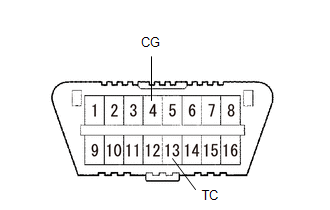
(2) Using SST, connect terminals TC and CG of the DLC3.
SST: 09843-18040
NOTICE:
Connect the terminals to the correct positions to avoid a malfunction.
(b) Check the DTCs (History trouble codes).
(1) Using SST, connect terminals TC and CG of the DLC3.
SST: 09843-18040
NOTICE:
Connect the terminals to the correct positions to avoid a malfunction.
(2) Turn the ignition switch to ON, and wait for approximately 60 seconds.
(c) Read the DTCs.

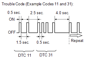
(1) Read the blinking patterns of the DTCs. As examples, the blinking patterns for the normal system code and trouble codes 11 and 31 are shown in the illustration.
- Normal system code indication (without history trouble code)
The light blinks twice per second.
- Normal system code indication (with history trouble code)
When the history trouble code is stored in the center airbag sensor assembly, the light blinks only once per second.
- Trouble code indication
The first blinks indicate the first DTC. The second blinks occur after a 1.5-second pause.
NOTICE:
When a DTC includes a letter (such as DTC 8A), the light blinks 8 times and then it blinks 10 times to indicate the A after a 1.5-second pause.
Comparison Table|
Number of Blinks |
Indicated Letter |
|---|---|
|
10 |
A |
|
11 |
B |
|
12 |
C |
|
13 |
D |
|
14 |
E |
|
15 |
F |
If there is more than 1 code, there will be a 2.5-second pause between each code. After all codes are shown, there will be a 4.0-second pause, and then all codes will be repeated.
HINT:
- If 2 or more malfunctions are found, the indication begins with the smaller-numbered code.
- If DTCs are indicated without connecting the terminals, proceed to TC
and CG Terminal Circuit (See page
.gif) ).
).
2. DTC CLEAR (USING SST CHECK WIRE)
(a) Clear the DTCs.
(1) When the ignition switch is turned off, the DTCs are cleared.
HINT:
Depending on the DTC, the code may not be cleared by turning off the ignition switch. In this case, proceed to the next procedure.
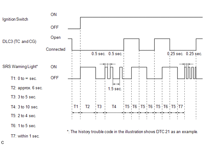
(2) Using SST, connect terminals TC and CG of the DLC3, and then turn the ignition switch to ON.
SST: 09843-18040
(3) Disconnect terminal TC of the DLC3 within 3 to 10 seconds after the DTCs are output, and check if the SRS warning light comes on after 3 seconds.
(4) Within 2 to 4 seconds after the SRS warning light comes on, connect terminals TC and CG of the DLC3.
(5) The SRS warning light should go off within 2 to 4 seconds after connecting terminals TC and CG of the DLC3. Then, disconnect terminal TC within 2 to 4 seconds after the SRS warning light goes off.
(6) The SRS warning light comes on again within 2 to 4 seconds after disconnecting terminal TC. Then, reconnect terminals TC and CG within 2 to 4 seconds after the SRS warning light comes on.
(7) Check if the SRS warning light goes off within 2 to 4 seconds after connecting terminals TC and CG of the DLC3. Also check if the normal system code is output within 1 second after the SRS warning light goes off.
If DTCs are not cleared, repeat this procedure until the codes are cleared.
3. DTC CHECK (USING TECHSTREAM)
(a) Turn the ignition switch off.
(b) Connect the Techstream to the DLC3.
(c) Turn the ignition switch to ON.
(d) Turn the Techstream on.
(e) Enter the following menus: Body Electrical / SRS Airbag / Trouble Codes.
(f) Check the DTCs by following the prompts on the Techstream screen.
HINT:
Refer to the Techstream operator's manual for further details.
4. DTC CLEAR (USING TECHSTREAM)
(a) Turn the ignition switch off.
(b) Connect the Techstream to the DLC3.
(c) Turn the ignition switch to ON.
(d) Turn the Techstream on.
(e) Enter the following menus: Body Electrical / SRS Airbag / Trouble Codes.
(f) Clear the DTCs by following the prompts on the Techstream screen.
HINT:
Refer to the Techstream operator's manual for further details.
 Diagnosis System
DIAGNOSIS SYSTEM
1. CHECK DLC3
(a) Check the DLC3 (See page ).
2. FUNCTION OF SRS WARNING LIGHT
(a) Primary check
(1) Turn the ignition switch off. Wait for at least 2 seconds, then turn the
i ...
 Check Mode Procedure
CHECK MODE PROCEDURE
1. CHECK MODE (SIGNAL CHECK): DTC CHECK
(a) Turn the ignition switch off.
(b) Connect the Techstream to the DLC3.
(c) Turn the ignition switch to ON.
(d) Turn the Techstream ...
Other materials about Toyota Venza:
Sound Signal Circuit between Radio Receiver and Stereo Jack Adapter
DESCRIPTION
The No. 1 stereo jack adapter assembly sends the sound signal from an
external device to the radio and display receiver assembly via this circuit.
The sound signal that has been sent is amplified by the radio and display
receiver ...
Removal
REMOVAL
PROCEDURE
1. REMOVE INSTRUMENT PANEL REINFORCEMENT ASSEMBLY WITH AIR CONDITIONING UNIT
(See page )
2. REMOVE COOL AIR INTAKE DUCT SEAL
3. REMOVE INLET NO. 2 AIR CLEANER
4. REMOVE AIR CLEANER CAP WITH HOSE
5. REMOVE AIR CLEANER CASE
...
Antenna location and effective range
- Antenna location
1. Antennas outside cabin
2. Antennas inside cabin
3. Antenna outside luggage compartment
- Effective range (areas within which the electronic key is detected)
When locking or unlocking the doors The system can be operat ...

0.1121