Toyota Venza: Door Control Switch
Components
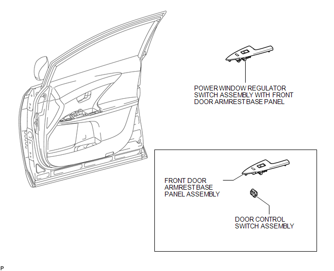
COMPONENTS
ILLUSTRATION
Inspection
INSPECTION
PROCEDURE
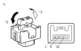
1. INSPECT DOOR CONTROL SWITCH ASSEMBLY
|
(a) Measure the resistance according to the value(s) in the table below. Standard Resistance:
If the result is not as specified, replace the door control switch assembly |
|
Removal
REMOVAL
PROCEDURE
1. REMOVE POWER WINDOW REGULATOR SWITCH ASSEMBLY WITH FRONT DOOR ARMREST BASE PANEL
.gif)
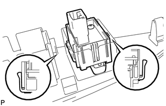
2. REMOVE DOOR CONTROL SWITCH ASSEMBLY
|
(a) Disengage the 2 claws and remove the door control switch assembly. |
|
Installation
INSTALLATION
PROCEDURE
1. INSTALL DOOR CONTROL SWITCH ASSEMBLY
|
(a) Engage the 2 claws and install the door control switch assembly. |
|
.png)
2. INSTALL POWER WINDOW REGULATOR SWITCH ASSEMBLY WITH FRONT DOOR ARMREST BASE PANEL
.gif)
 Installation
INSTALLATION
PROCEDURE
1. INSTALL DOOR CONTROL RECEIVER
(a) Install the door control receiver with the bolt.
(b) Connect the connector.
2 ...
 Door Control Transmitter(w/ Smart Key System)
Components
COMPONENTS
ILLUSTRATION
Removal
REMOVAL
PROCEDURE
1. REMOVE TRANSMITTER BATTERY
Inspection
INSPECTION
PROCEDURE
1. INSPECT DOOR CONTROL TRANSMITTER
(a) Inspect operati ...
Other materials about Toyota Venza:
System Description
SYSTEM DESCRIPTION
1. GENERAL
The rear window defogger wires are attached to the inside of the rear window
and defog the window surface quickly by pressing the rear window defogger switch
on the air conditioning control assembly. The indicator light is i ...
Installation
INSTALLATION
CAUTION / NOTICE / HINT
HINT:
Use the same procedure for the LH side and RH side.
The following procedure listed below is for the LH side.
PROCEDURE
1. SECURE FRONT SHOCK ABSORBER ASSEMBLY
(a) Install the bolt an ...
Open or Short Circuit in ABS Solenoid Relay Circuit (C0278/11)
DESCRIPTION
The ABS solenoid relay supplies power to the ABS solenoid and TRAC solenoid.
The solenoid relay is turned on 1.5 seconds after the ignition switch is turned
to ON, and is turned off if an open or short in the solenoid is detected by self
diag ...

0.1317