Toyota Venza: Disassembly
DISASSEMBLY
PROCEDURE
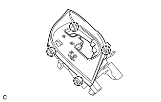
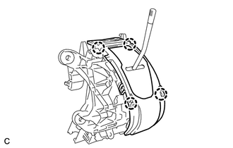
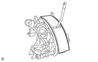
1. REMOVE POSITION INDICATOR HOUSING SUB-ASSEMBLY
(a) Remove the shift lever cap from the position indicator housing sub-assembly.
|
(b) Disengage the 4 claws and remove the position indicator housing sub-assembly. |
|
2. REMOVE POSITION INDICATOR LIGHT GUIDE
|
(a) Disengage the 4 claws and remove the position indicator connector and position indicator light guide. |
|
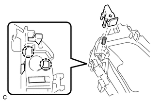
3. REMOVE SHIFT LOCK RELEASE BUTTON
|
(a) Disengage the 2 claws to remove the shift lock release button and compression spring. |
|
4. REMOVE INDICATOR LIGHT WIRE SUB-ASSEMBLY
|
(a) Remove the indicator light wire sub-assembly from the position indicator light guide. |
|
5. REMOVE POSITION INDICATOR LIGHT BULB
(a) Remove the position indicator light cap from the position indicator light bulb.
(b) Remove the position indicator light bulb from the indicator light wire sub-assembly.
6. REMOVE UPPER POSITION INDICATOR HOUSING
|
(a) Detach the 4 claws and remove the upper position indicator housing from the lower position indicator housing. |
|
7. REMOVE POSITION INDICATOR SLIDE COVER
|
(a) Remove the position indicator slide cover from the lower position indicator housing. |
|
8. REMOVE NO. 2 POSITION INDICATOR SLIDE COVER
(a) Remove the No. 2 position indicator slide cover from the position indicator slide cover.
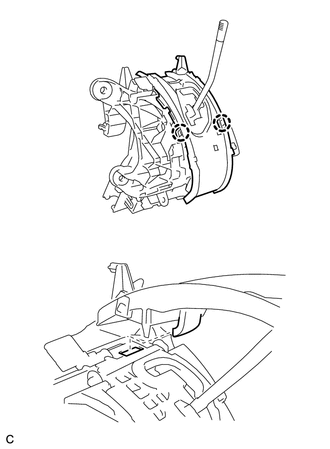
9. REMOVE LOWER POSITION INDICATOR HOUSING
|
(a) Detach the 2 claws and remove the lower position indicator housing from the shift lock control unit assembly. |
|
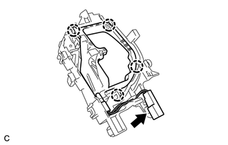
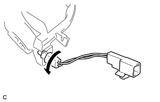
10. REMOVE SHIFT LOCK CONTROL COMPUTER SUB-ASSEMBLY
|
(a) Disconnect the connector from the shift lock control computer sub-assembly. |
|
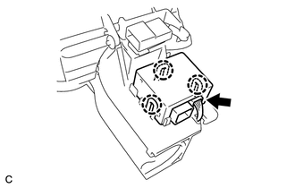
(b) Detach the 3 claws and remove the shift lock control computer sub-assembly.
 On-vehicle Inspection
ON-VEHICLE INSPECTION
PROCEDURE
1. INSPECT SHIFT LOCK CONTROL UNIT ASSEMBLY
(a) Inspect the shift lock operation.
(1) Move the shift lever to P.
(2) Turn the ignition switch off.
(3) Check that ...
 Removal
REMOVAL
PROCEDURE
1. DISCONNECT CABLE FROM NEGATIVE BATTERY TERMINAL
NOTICE:
When disconnecting the cable, some systems need to be initialized after the cable
is reconnected (See page ).
2. RE ...
Other materials about Toyota Venza:
Operation Check
OPERATION CHECK
1. INSPECT ILLUMINATED ENTRY SYSTEM OPERATION
NOTICE:
Perform this inspection with the customize parameters at the initial setting.
HINT:
The interior light control illuminates the lights below.
Transponder Key Amplifier*1
Roof ...
Terminals Of Ecu
TERMINALS OF ECU
1. CHECK POWER STEERING ECU
HINT:
As connector z8 uses a lock lever, each terminal cannot be checked while the
connector is still connected to the power steering ECU.
Terminal No. (Symbol)
Wiring Color
...
Removal
REMOVAL
CAUTION / NOTICE / HINT
HINT:
Use the same procedure for the RH side and LH side.
The procedure listed below is for the LH side.
PROCEDURE
1. PRECAUTION
CAUTION:
Be sure to read Precaution thoroughly before servicing (See page
...

0.1309