Toyota Venza: Disassembly
DISASSEMBLY
CAUTION / NOTICE / HINT
HINT:
- Use the same procedure for the RH side and the LH side.
- The procedure listed below is for the LH side.
PROCEDURE
1. REMOVE REAR WHEEL
2. REMOVE REAR AXLE SHAFT NUT (for AWD)
NOTICE:
Perform this procedure only when the No. 1 parking brake shoe hold down spring pin is replaced.
HINT:
See page .gif) .
.
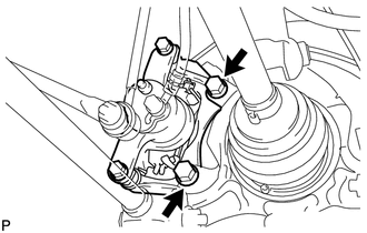
3. SEPARATE REAR DISC BRAKE CALIPER ASSEMBLY
|
(a) Remove the 2 bolts and rear disc brake caliper assembly. NOTICE:
|
|
4. REMOVE REAR DISC
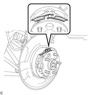
5. REMOVE NO. 1 PARKING BRAKE SHOE RETURN TENSION SPRING
|
(a) Remove the 2 No. 1 parking brake shoe return tension springs. |
|
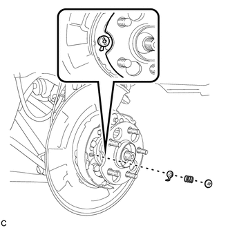
6. SEPARATE NO. 1 PARKING BRAKE SHOE ASSEMBLY
|
(a) Remove the No. 1 parking brake shoe hold down spring cup, parking brake shoe hold down spring and No. 2 parking brake shoe hold down spring cup, and separate the No. 1 parking brake shoe assembly from the backing plate. |
|
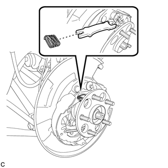
7. REMOVE PARKING BRAKE SHOE STRUT
|
(a) Remove the parking brake shoe strut and the parking brake shoe strut compression spring. |
|
8. SEPARATE NO. 2 PARKING BRAKE SHOE ASSEMBLY
|
(a) Remove the No. 1 parking brake shoe hold down spring cup, parking brake shoe hold down spring and No. 2 parking brake shoe hold down spring cup, and separate the No. 2 parking brake shoe assembly from the backing plate. |
|
9. REMOVE PARKING BRAKE SHOE ADJUSTING SCREW SET
|
(a) Remove the parking brake shoe adjusting screw set. |
|
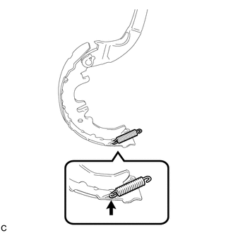
10. REMOVE NO. 1 PARKING BRAKE SHOE ASSEMBLY
|
(a) Separate the No. 2 parking brake shoe return tension spring and remove the No. 1 parking brake shoe assembly. |
|
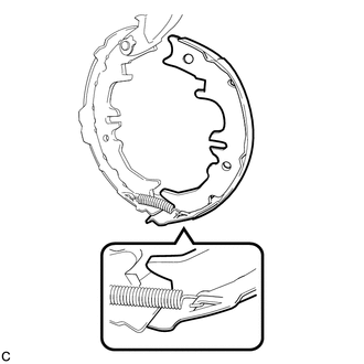
11. REMOVE NO. 2 PARKING BRAKE SHOE RETURN TENSION SPRING
|
(a) Remove the No. 2 parking brake shoe return tension spring from the No. 2 parking brake shoe assembly. |
|
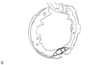
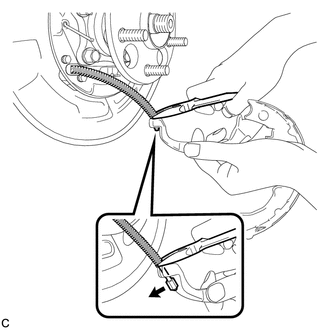
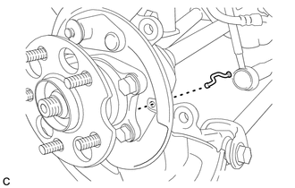
12. REMOVE NO. 2 PARKING BRAKE SHOE ASSEMBLY WITH PARKING BRAKE SHOE LEVER
|
(a) Using needle-nose pliers, separate the No. 3 parking brake cable assembly from the parking brake shoe lever as shown in the illustration. NOTICE: Be careful not to damage the No. 3 parking brake cable assembly. |
|
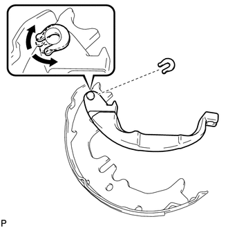
13. REMOVE PARKING BRAKE SHOE LEVER
|
(a) Remove the C-washer, shim and the parking brake shoe lever from the No. 2 parking brake shoe assembly. HINT: The shim is installed only when a clearance adjustment between the parking brake lever and parking brake shoe C-washer is necessary. Therefore, some models may have no shim. |
|
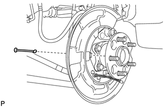
14. REMOVE PARKING BRAKE SHOE GUIDE PLATE SET BOLT
|
(a) Remove the parking brake shoe guide plate set bolt and the parking brake shoe guide plate. |
|
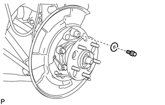
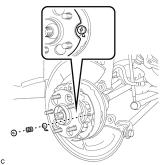
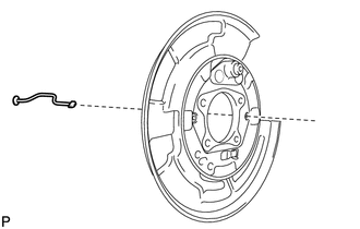
15. REMOVE NO. 1 PARKING BRAKE SHOE HOLD DOWN SPRING PIN (for 2WD)
|
(a) Remove the No. 1 parking brake shoe hold down spring pin. |
|
16. REMOVE NO. 2 PARKING BRAKE SHOE HOLD DOWN SPRING PIN (for AWD)
|
(a) Remove the No. 2 parking brake shoe hold down spring pin. |
|
17. REMOVE REAR AXLE HUB AND BEARING ASSEMBLY (for 2WD)
NOTICE:
Perform this procedure only when the No. 2 parking brake shoe hold down spring pin is replaced.
HINT:
See page .
18. REMOVE REAR AXLE HUB AND BEARING ASSEMBLY (for AWD)
NOTICE:
Perform this procedure only when the No. 1 parking brake shoe hold down spring pin is replaced.
HINT:
See page .
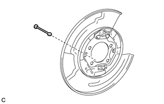
19. REMOVE NO. 2 PARKING BRAKE SHOE HOLD DOWN SPRING PIN (for 2WD)
|
(a) Remove the No. 2 parking brake shoe hold down spring pin. |
|
20. REMOVE NO. 1 PARKING BRAKE SHOE HOLD DOWN SPRING PIN (for AWD)
|
(a) Remove the No. 1 parking brake shoe hold down spring pin. |
|
 Components
COMPONENTS
ILLUSTRATION
ILLUSTRATION
ILLUSTRATION
ILLUSTRATION
ILLUSTRATION
ILLUSTRATION
ILLUSTRATION
...
 Inspection
INSPECTION
PROCEDURE
1. INSPECT BRAKE DISC INSIDE DIAMETER
(a) Using a brake drum gauge or an equivalent tool, measure the inside
diameter of the disc.
Standard inside diameter of ...
Other materials about Toyota Venza:
Passenger Airbag ON/OFF Indicator Circuit Malfunction (B1660/43)
DESCRIPTION
The passenger airbag ON/OFF indicator circuit consists of the center airbag sensor
assembly and accessory meter assembly (passenger airbag ON/OFF indicator).
The passenger airbag ON/OFF indicator indicates the operation condition of the
front ...
Master Cylinder Pressure Sensor Malfunction (C1246/46,C1281/81)
DESCRIPTION
Master cylinder pressure sensor is connected to the skid control ECU in the brake
actuator assembly.
DTC C1281/81 will be cleared when the master cylinder pressure sensor sends a
master cylinder pressure signal or when Test Mode ends. DTC C12 ...
Tire information
Typical tire symbols
►Standard tire
►Compact spare tire
1. Tire size
2. DOT and Tire Identification Number (TIN)
3. Location of treadwear indicators
4. Tire ply composition and materials Plies are layers of rubber-coated parallel
cords ...

0.1665