Toyota Venza: Disassembly
DISASSEMBLY
PROCEDURE
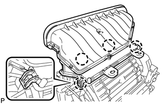
1. REMOVE NO. 1 AIR DUCT SUB-ASSEMBLY
|
(a) Disengage the 4 claws and remove the No. 1 air duct sub-assembly. |
|
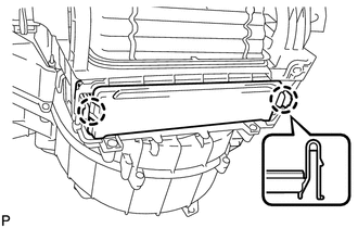
2. REMOVE AIR FILTER COVER PLATE
|
(a) Disengage the 2 claws and remove the air filter cover plate. |
|
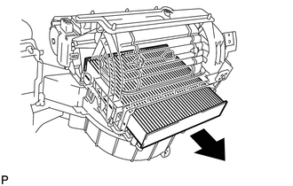
3. REMOVE CLEAN AIR FILTER
|
(a) Remove the clean air filter as shown in the illustration. |
|
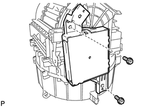
4. REMOVE AIR CONDITIONING AMPLIFIER ASSEMBLY
|
(a) Remove the 2 screws and air conditioning amplifier assembly. |
|
5. REMOVE AIR INLET SERVO MOTOR SUB-ASSEMBLY
|
(a) Remove the screw. |
|
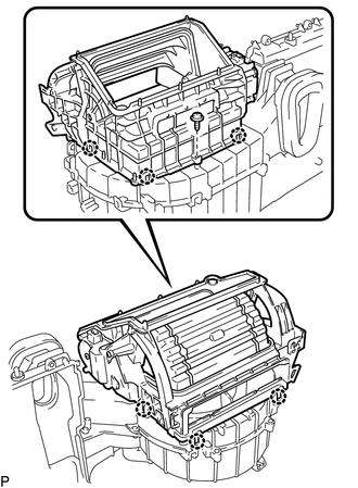
(b) Disengage the 6 claws and remove the blower case.
|
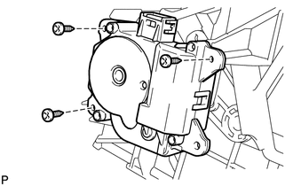
(c) Remove the 3 screws and air inlet servo motor sub-assembly. |
|
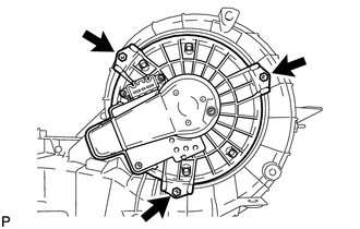
6. REMOVE FRONT BLOWER MOTOR SUB-ASSEMBLY
|
(a) Remove the 3 screws and front blower motor sub-assembly. |
|
 Removal
REMOVAL
PROCEDURE
1. REMOVE AIR CONDITIONING UNIT ASSEMBLY
(See page )
2. REMOVE NO. 1 FINISH PANEL MOUNTING BRACKET
3. REMOVE NO. 2 FINISH PANEL MOUNTING BRACKET
4. REMOVE NO. 3 AIR DUCT ...
 Reassembly
REASSEMBLY
PROCEDURE
1. INSTALL FRONT BLOWER MOTOR SUB-ASSEMBLY
(a) Install the front blower motor sub-assembly with the 3 screws.
2. INST ...
Other materials about Toyota Venza:
Power Back Door cannot be Operated Using Any Switch
DESCRIPTION
When the power back door cannot be operated using any switch, one of the following
may be the cause: 1) initialization of the power back door ECU (power back door
motor unit), 2) power back door touch sensor circuit, 3) power back door main sw ...
Adjustment
ADJUSTMENT
CAUTION / NOTICE / HINT
HINT:
It is possible that a bulb is incorrectly installed, affecting headlight aim.
Bulb installation should be considered prior to performing the adjustment procedure.
PROCEDURE
1. PREPARE VEHICLE FOR HEADLIGHT AIM AD ...
Installation
INSTALLATION
PROCEDURE
1. INSTALL CHARCOAL CANISTER LEAK DETECTION PUMP SUB-ASSEMBLY
(a) Engage the 2 claws to install a new charcoal canister leak detection
pump sub-assembly to the charcoal canister assembly.
NOTICE:
Do n ...

0.1357