Toyota Venza: Disassembly
DISASSEMBLY
PROCEDURE
1. REMOVE TAIL AND STOP LIGHT BULB
|
(a) Turn the tail and stop light bulb and the rear combination light socket and wire in the direction indicated by the arrow shown in the illustration, and remove them as a unit. |
|
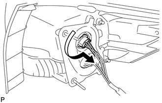
(b) Remove the tail and stop light bulb from the rear combination light socket and wire.
2. REMOVE REAR TURN SIGNAL LIGHT BULB
|
(a) Turn the rear turn signal light bulb and rear combination light socket and wire in the direction indicated by the arrow shown in the illustration, and remove them as a unit. |
|
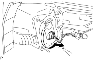
(b) Remove the rear turn signal light bulb from the rear combination light socket and wire.
3. REMOVE REAR BUMPER UPPER RETAINER
|
(a) Remove the 2 screws. |
|
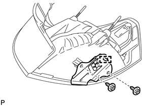
(b) Disengage the guide and remove the rear bumper upper retainer.
 Removal
REMOVAL
PROCEDURE
1. REMOVE REAR DOOR SCUFF PLATE
2. DISCONNECT REAR DOOR OPENING TRIM WEATHERSTRIP
3. REMOVE TONNEAU COVER ASSEMBLY (w/ Tonneau Cover)
4. REMOVE DECK BOARD ASSEMBLY
...
 Reassembly
REASSEMBLY
PROCEDURE
1. INSTALL REAR BUMPER UPPER RETAINER
(a) Engage the guide.
(b) Install the rear bumper upper retainer with the 2 scr ...
Other materials about Toyota Venza:
Unlock Warning Switch Circuit
DESCRIPTION
The key unlock warning switch assembly turns on when the ignition key is inserted
into the ignition key cylinder and turns off when the ignition key is removed.
The main body ECU (driver side junction block assembly) operates the key confinemen ...
Calibration
CALIBRATION
1. ROTATION ANGLE SENSOR INITIALIZATION AND TORQUE SENSOR ZERO POINT CALIBRATION
NOTICE:
Clear the rotation angle sensor calibration value, initialize the rotation angle
sensor, and calibrate the torque sensor zero point if any of the followin ...
Mass Air Flow Circuit Range / Performance Problem (P0101)
DESCRIPTION
Refer to DTC P0102 (See page ).
DTC No.
DTC Detection Condition
Trouble Area
P0101
All of the following conditions are met (2 trip detection logic):
(a) The engine is running.
(b ...

0.1164