Toyota Venza: Disassembly
DISASSEMBLY
PROCEDURE
1. REMOVE NO. 1 ULTRASONIC SENSOR (w/ Intuitive Parking Assist System)
.gif)
2. REMOVE NO. 2 ULTRASONIC SENSOR RETAINER (w/ Intuitive Parking Assist System)
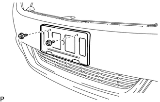
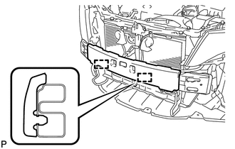
3. REMOVE FRONT LICENSE PLATE BRACKET
|
(a) Remove the 2 screws and front license plate bracket. |
|
4. REMOVE FOG LIGHT ASSEMBLY LH
5. REMOVE FOG LIGHT ASSEMBLY RH
HINT:
Use the same procedure for the RH side and LH side.
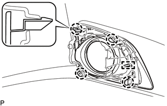
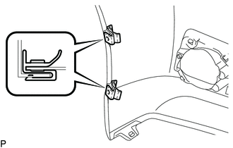
6. REMOVE FRONT BUMPER HOLE COVER ASSEMBLY LH
|
(a) Disengage the 4 claws and pin, and remove the front bumper hole cover assembly LH. |
|
7. REMOVE FRONT BUMPER HOLE COVER ASSEMBLY RH
HINT:
Use the same procedure for the RH side and LH side.
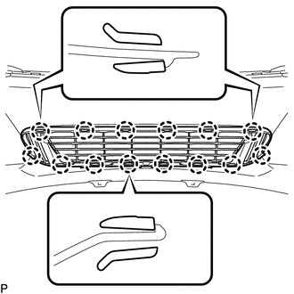
8. REMOVE NO. 1 LOWER RADIATOR GRILLE
|
(a) Disengage the 14 claws and remove the No. 1 lower radiator grille. |
|
9. REMOVE FRONT BUMPER MOULDING
|
(a) Remove the 2 screws. |
|
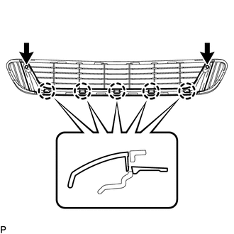
(b) Disengage the 5 claws and remove the front bumper moulding.
10. REMOVE FRONT FENDER LINER RETAINER
|
(a) Remove the 2 front fender liner retainers. HINT: Use the same procedure for the RH side and LH side. |
|
11. REMOVE FRONT BUMPER ENERGY ABSORBER
|
(a) Disengage the 2 guides and remove the front bumper energy absorber. |
|
12. REMOVE FRONT BUMPER REINFORCEMENT SUB-ASSEMBLY
|
(a) Disengage the 4 clamps. |
|
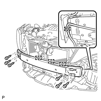
(b) Remove the 6 bolts and front bumper reinforcement sub-assembly.
13. REMOVE FRONT BUMPER SIDE RETAINER LH
|
(a) Remove the bolt and screw. Text in Illustration
|
|
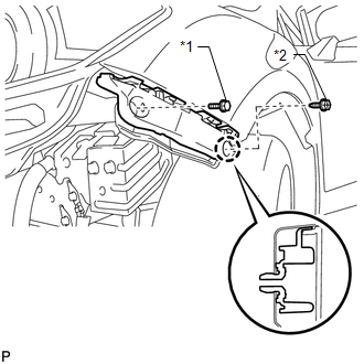
(b) Disengage the claw and remove the front bumper side retainer LH.
14. REMOVE FRONT BUMPER SIDE RETAINER RH
HINT:
Use the same procedure for the RH side and LH side.
 Removal
REMOVAL
PROCEDURE
1. REMOVE COOL AIR INTAKE DUCT SEAL
(a) Using a clip remover, remove the 12 clips and cool air intake duct
seal.
2. ...
 Reassembly
REASSEMBLY
PROCEDURE
1. INSTALL FRONT BUMPER SIDE RETAINER LH
(a) Engage the claw and install the front bumper side retainer LH.
Text in Illustration
*1
...
Other materials about Toyota Venza:
Speaker Output Short (B15C3)
DESCRIPTION
This DTC is stored when a malfunction occurs in the speakers.
DTC No.
DTC Detection Condition
Trouble Area
B15C3
A short is detected in the speaker output circuit
...
Diagnosis System
DIAGNOSIS SYSTEM
1. CHECK DLC3
(a) Check the DLC3 (See page ).
2. FUNCTION OF SRS WARNING LIGHT
(a) Primary check
(1) Turn the ignition switch off. Wait for at least 2 seconds, then turn the
ignition switch to ON. The SRS warning light comes on for app ...
Installation
INSTALLATION
CAUTION / NOTICE / HINT
NOTICE:
Always use a new grommet and valve core when installing the tire pressure
warning valve and transmitter.
Check that the washer and nut are not damaged, and replace them if necessary.
Write ...

0.1328