Toyota Venza: Disassembly
DISASSEMBLY
CAUTION / NOTICE / HINT
NOTICE:
When using a vise, do not overtighten it.
PROCEDURE
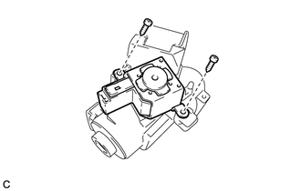
1. REMOVE STEERING LOCK ACTUATOR ASSEMBLY (w/ Smart Key System)
(a) Secure the steering column assembly in a vise.
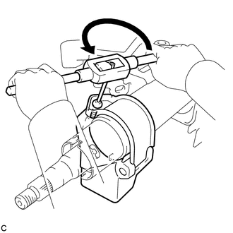
(b) Using a center punch, mark the center of the tapered-head bolt.
(c) Using a 3 to 4 mm (0.118 to 0.157 in.) diameter drill bit, drill a hole in the tapered-head bolt.
|
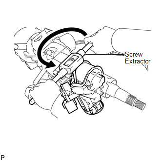
(d) Using a screw extractor, remove the tapered-head bolt, and then remove the steering lock actuator assembly from the steering column assembly. |
|
2. REMOVE STEERING COLUMN UPPER WITH SWITCH BRACKET ASSEMBLY (w/o Smart Key System)
(a) Secure the steering column assembly in a vise.
(b) Using a center punch, mark the center of the tapered-head bolt.
(c) Using a 3 to 4 mm (0.118 to 0.157 in.) diameter drill bit, drill a hole in the tapered-head bolt.
|
(d) Using a screw extractor, remove the tapered-head bolt, and then remove the steering column upper with switch bracket assembly from the steering column assembly. |
|
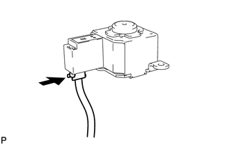
3. REMOVE IGNITION OR STARTER SWITCH ASSEMBLY (w/o Smart Key System)
|
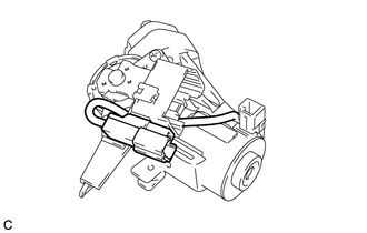
(a) Remove the solenoid wire connector from the ignition or starter switch assembly. |
|
|
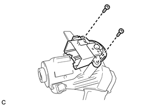
(b) Remove the 2 screws and the ignition or starter switch assembly from the steering column upper bracket. |
|
4. REMOVE KEY INTER LOCK SOLENOID (w/o Smart Key System)
|
(a) Remove the 2 screws and the key interlock solenoid from the steering column upper bracket. |
|
|
(b) Disconnect the solenoid wire connector from the key interlock solenoid. |
|
5. REMOVE SOLENOID WIRE (w/o Smart Key System)
|
(a) Remove the solenoid wire from the steering column upper bracket. |
|
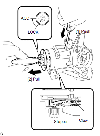
6. REMOVE IGNITION SWITCH LOCK CYLINDER ASSEMBLY (w/o Smart Key System)
(a) Turn the ignition switch lock cylinder assembly to the ACC position.
|
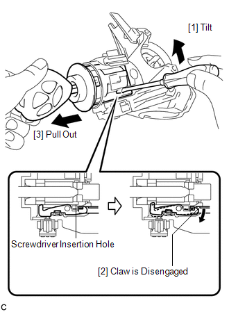
(b) Insert a screwdriver into the hole of the steering column upper with switch bracket assembly as shown in the illustration. Pull the ignition switch lock cylinder assembly until its claw contacts the stopper of the steering column upper with switch bracket assembly. NOTICE: Make sure to pull the ignition switch lock cylinder assembly until its claw contacts the stopper of the steering column upper with switch bracket assembly. Failure to do so will affect later work operations. |
|
|
(c) Insert a screwdriver into the hole of the steering column upper with switch bracket assembly. Tilt the screwdriver as shown in the illustration to disengage the claw of the ignition switch lock cylinder assembly, and pull out the ignition switch lock cylinder assembly. |
|
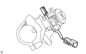
7. REMOVE UNLOCK WARNING SWITCH ASSEMBLY (w/o Smart Key System)
|
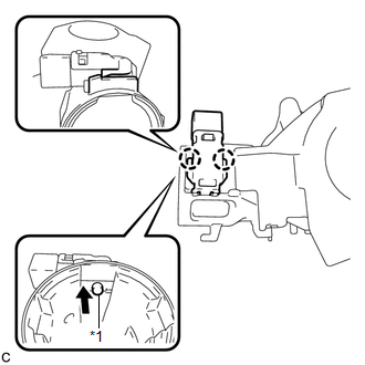
(a) Remove the unlock warning switch assembly by pushing up the center part and releasing the 2 claws. Text in Illustration
|
|
 Removal
REMOVAL
CAUTION / NOTICE / HINT
CAUTION:
Some of these service operations affect the SRS airbag system. Read the precautionary
notices concerning the SRS airbag system before servicing the steeri ...
 Inspection
INSPECTION
PROCEDURE
1. INSPECT PRELOAD
(a) Secure the steering column assembly in a vise.
Text in Illustration
*1
Service Nut
...
Other materials about Toyota Venza:
How To Proceed With Troubleshooting
CAUTION / NOTICE / HINT
HINT:
*: Use the Techstream
PROCEDURE
1.
VEHICLE BROUGHT TO WORKSHOP
NEXT
2.
CUSTOMER PROBLEM ANALYSIS
...
System Description
SYSTEM DESCRIPTION
1. POWER DOOR LOCK CONTROL SYSTEM DESCRIPTION
(a) The power door lock system locks/unlocks all doors.
The door control switch sends "lock/unlock" request signals to the main body
ECU (driver side junction block assembly). Then ...
Pressure Control Solenoid "C" Performance (Shift Solenoid Valve SL3) (P0796)
SYSTEM DESCRIPTION
The TCM uses the vehicle speed signal and signals from the transmission speed
sensors (NC, NT) to detect the actual gear (1st, 2nd, 3rd, 4th, 5th or 6th gear).
Then the TCM compares the actual gear with the shift schedule in the TCM memo ...

0.1305