Toyota Venza: Diagnosis System
DIAGNOSIS SYSTEM
1. DESCRIPTION
(a) Air conditioning system data and the Diagnostic Trouble Codes (DTCs) can be read through the Data Link Connector 3 (DLC3) of the vehicle. When the system seems to be malfunctioning, use the Techstream to check for malfunctions and perform troubleshooting.
2. CHECK DLC3
(a) Check the DLC3 (See page .gif) ).
).
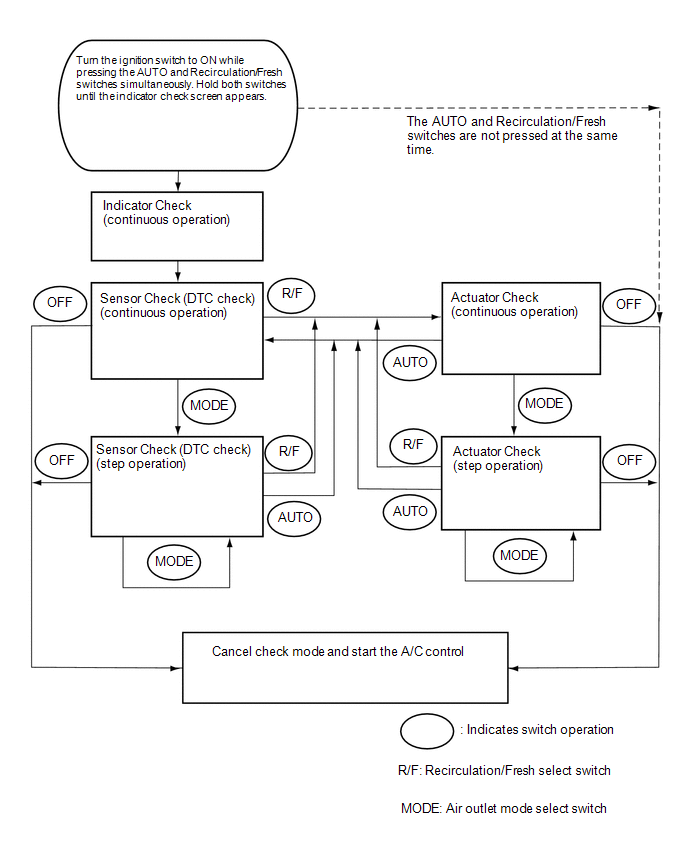
3. LIST OF OPERATION METHODS
(a) By operating each of the air conditioning control switches as shown in the diagram below, it is possible to enter diagnostic check mode.
4. INDICATOR CHECK
(a) Turn the ignition switch off.
(b) Turn the ignition switch to ACC and wait at least 5 seconds.
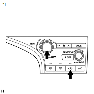
(c) Turn the ignition switch to ON while pressing the A/C control "AUTO" switch and "Recirculation/Fresh" switch simultaneously. Hold both switches until the indicator check screen appears.
 Text in Illustration
|
*1 |
Air Conditioning Control Assembly |
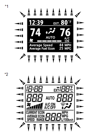
(d) The indicator check is automatically performed when panel diagnosis is activated. Check that the indicators light up and go off 4 times at 1 second intervals continuously.
HINT:
- The sensor check automatically starts when the indicator check is completed.
- Press the "OFF" switch to cancel the check mode.
|
*1 |
Accessory Meter Assembly (TFT) |
|
*2 |
Accessory Meter Assembly (LCD) |
|
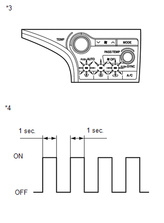
*3 |
Air Conditioning Control Assembly |
|
*4 |
Indicator Blinking Pattern |
5. SENSOR CHECK (DTC CHECK)
(a) Start the engine and warm it up.
(b) Perform the indicator check.
HINT:
After the indicator check is completed, the system enters DTC check mode automatically.
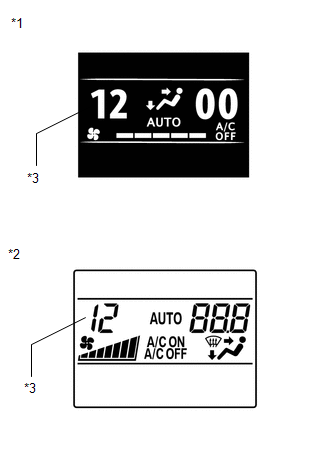
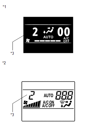
(c) Read the DTC displayed on the accessory meter display.
NOTICE:
In sensor check mode, which is automatically entered after indicator check mode, troubleshooting may be partially performed. Be sure to perform the actuator check, and then the sensor check again.
HINT:
Refer to Diagnostic Trouble Code Chart for details of the codes (See page
).
- When there are no problems, DTC 00 is output.
- As an example, the illustration shows that display DTC 12 is output.
|
*1 |
Accessory Meter Assembly (TFT) |
|
*2 |
Accessory Meter Assembly (LCD) |
|
*3 |
DTC |
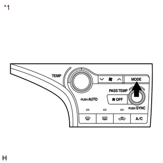
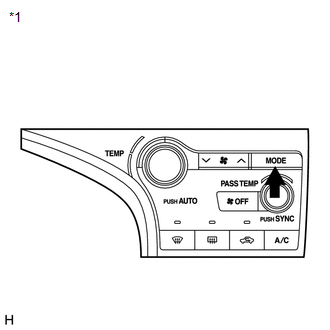
(d) If the steps are difficult to read because they change automatically, press the "MODE" switch to display the steps one at a time so that they can be read easily. The items are displayed step by step each time the "MODE" switch is pressed.
HINT:
- Press the "OFF" switch to finish panel diagnosis.
- Press the "Recirculation/Fresh" switch to enter actuator check mode.
|
*1 |
Air Conditioning Control Assembly |
(e) Clear the DTC
(1) During the sensor check, press the "Defroster" switch and "MODE" switch simultaneously.
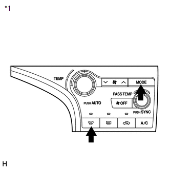 Text in Illustration
|
*1 |
Air Conditioning Control Assembly |
6. ACTUATOR CHECK
(a) Start the engine and warm it up.
(b) Perform the indicator check.
(c) Press the "Recirculation/Fresh" switch to perform the actuator check.
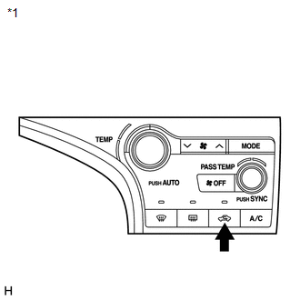
HINT:
Be sure to perform the actuator check after starting the engine.
Text in Illustration|
*1 |
Air Conditioning Control Assembly |
(d) As the actuator check is repeated from steps 1 to 10 at 1 second intervals, check the temperature and air flow visually and by hand.
HINT:
- The display blinks at 1 second intervals in the step operation.
- Press the "OFF" switch to finish panel diagnosis.
- Press the "AUTO" switch to enter sensor check mode.
|
*1 |
Accessory Meter Assembly (TFT) |
|
*2 |
Accessory Meter Assembly (LCD) |
|
*3 |
Display Code |
|
Step No. |
Display Code |
Condition |
||||
|---|---|---|---|---|---|---|
|
Blower Level |
Air Mix Damper |
Airflow Vent |
Air Inlet Damper |
Compressor |
||
|
1 |
0 |
0 |
0% open |
FACE |
FRESH |
off |
|
2 |
1 |
1 |
0% open |
FACE |
FRESH |
off |
|
3 |
2 |
17 |
0% open |
FACE |
RECIRCULATION / FRESH |
on |
|
4 |
3 |
17 |
0% open |
FACE |
RECIRCULATION |
on |
|
5 |
4 |
17 |
50% open |
B/L |
RECIRCULATION |
on |
|
6 |
5 |
17 |
50% open |
B/L |
RECIRCULATION |
on |
|
7 |
6 |
17 |
50% open |
FOOT |
FRESH |
on |
|
8 |
7 |
17 |
100% open |
FOOT-0 |
FRESH |
on |
|
9 |
8 |
17 |
100% open |
F/D |
FRESH |
on |
|
10 |
9 |
31 |
100% open |
DEF |
FRESH |
on |
(e) If the steps are difficult to read because they change automatically, press the "MODE" switch to display the steps one at a time so that they can be read easily. The items are displayed step by step each time the "MODE" switch is pressed.
HINT:
- Press the "OFF" switch to finish panel diagnosis.
- Press the "Recirculation/Fresh" switch to enter sensor check mode.
|
*1 |
Air Conditioning Control Assembly |
 Terminals Of Ecu
TERMINALS OF ECU
1. A/C AMPLIFIER
HINT:
Check from the rear of the connector while it is connected to the A/C amplifier.
Terminal No.
(Symbol)
Wiring Color
Te ...
 Dtc Check / Clear
DTC CHECK / CLEAR
1. DTC CHECK USING TECHSTREAM
(a) Connect the Techstream to the DLC3.
(b) Turn the ignition switch to ON.
(c) Turn the Techstream on.
(d) Enter the following menus: Body / Air C ...
Other materials about Toyota Venza:
On-vehicle Inspection
ON-VEHICLE INSPECTION
CAUTION / NOTICE / HINT
HINT:
Use the same procedure for the RH side and LH side.
The procedure listed below is for the LH side.
PROCEDURE
1. REMOVE REAR WHEEL
2. SEPARATE REAR DISC BRAKE CALIPER ASSEMBLY
3. RE ...
Ignition Coil "A" Primary / Secondary Circuit (P0351-P0354)
DESCRIPTION
HINT:
These DTCs indicate malfunctions relating to the primary circuit.
If DTC P0351 is output, check the No. 1 ignition coil circuit.
If DTC P0352 is output, check the No. 2 ignition coil circuit.
If DTC P0353 is output, c ...
Problem Symptoms Table
PROBLEM SYMPTOMS TABLE
HINT:
Use the table below to help determine the cause of problem symptoms.
If multiple suspected areas are listed, the potential causes of the symptoms
are listed in order of probability in the "Suspected Area" ...

0.1349