Toyota Venza: Diagnosis Circuit
DESCRIPTION
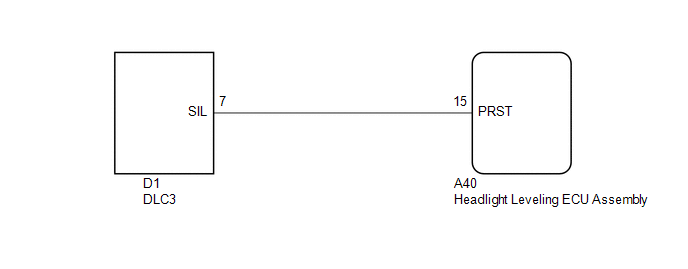
The headlight leveling ECU assembly outputs DTC information to the Techstream via this circuit.
WIRING DIAGRAM
PROCEDURE
|
1. |
CHECK HARNESS AND CONNECTOR (DLC3 - HEADLIGHT LEVELING ECU ASSEMBLY) |
(a) Disconnect the A40 headlight leveling ECU assembly connector.
(b) Measure the resistance according to the value(s) in the table below.
Standard Resistance:
|
Tester Connection |
Condition |
Specified Condition |
|---|---|---|
|
A40-15 (PRST) - D1-7 (SIL) |
Always |
Below 1 Ω |
|
A40-15 (PRST) - Body ground |
Always |
10 kΩ or higher |
| OK | .gif) |
PROCEED TO NEXT SUSPECTED AREA SHOWN IN PROBLEM SYMPTOMS TABLE |
| NG | |
REPAIR OR REPLACE HARNESS OR CONNECTOR |
 LVL Terminal Circuit
DESCRIPTION
By connecting terminals LVL and CG of the DLC3, the headlight leveling
ECU assembly initializes the height control sensor signal.
WIRING DIAGRAM
PROCEDURE
...

Other materials about Toyota Venza:
Installation
INSTALLATION
PROCEDURE
1. INSTALL ROOF HEADLINING ASSEMBLY (w/o Sliding Roof)
(a) Pull the roof headlining assembly into the vehicle through the back
door.
NOTICE:
Do not damage the roof headlining assembly or body interior.
...
Lost Communication with AFS ECU (U0182)
DESCRIPTION
DTC No.
DTC Detection Condition
Trouble Area
U0182
No communication from the AFS ECU continues.
AFS ECU branch wire or connector
Power source circuit of AFS E ...
Removal
REMOVAL
CAUTION / NOTICE / HINT
HINT:
Use the same procedure for the RH side and LH side.
The procedure listed below is for the LH side.
PROCEDURE
1. REMOVE REAR WHEEL
2. SEPARATE REAR SPEED SENSOR
(a) Remove the bolt and se ...

0.1623