Toyota Venza: Data Signal Circuit between Navigation Receiver Assembly and Stereo Jack Adapter
DESCRIPTION
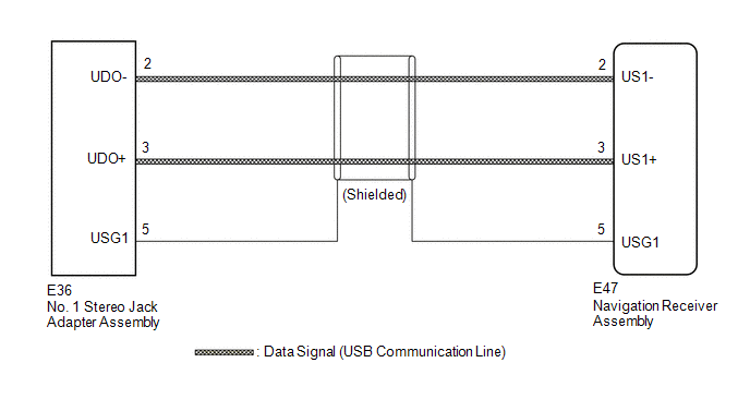
The No. 1 stereo jack adapter assembly sends the sound data signal or image data signal from a USB device to the navigation receiver assembly via this circuit.
WIRING DIAGRAM
PROCEDURE
|
1. |
CHECK HARNESS AND CONNECTOR (NAVIGATION RECEIVER ASSEMBLY - NO. 1 STEREO JACK ADAPTER ASSEMBLY) |
|
(a) Disconnect the E47 navigation receiver assembly connector. |
|
(b) Disconnect the E36 No. 1 stereo jack adapter assembly connector.
(c) Measure the resistance according to the value(s) in the table below.
Standard Resistance:
|
Tester Connection |
Condition |
Specified Condition |
|---|---|---|
|
E47-2 (US1-) - E36-2 (UDO-) |
Always |
Below 1 Ω |
|
E47-3 (US1+) - E36-3 (UDO+) |
Always |
Below 1 Ω |
|
E47-5 (USG1) - E36-5 (USG1) |
Always |
Below 1 Ω |
|
E47-2 (US1-) - Body ground |
Always |
10 kΩ or higher |
|
E47-3 (US1+) - Body ground |
Always |
10 kΩ or higher |
|
E47-5 (USG1) - Body ground |
Always |
10 kΩ or higher |
|
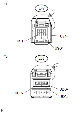
*a |
Front view of wire harness connector (to Navigation Receiver Assembly) |
|
*b |
Front view of wire harness connector (to No. 1 Stereo Jack Adapter Assembly) |
| OK | .gif) |
PROCEED TO NEXT SUSPECTED AREA SHOWN IN PROBLEM SYMPTOMS TABLE |
| NG | |
REPAIR OR REPLACE HARNESS OR CONNECTOR |
 Data Signal Circuit between Navigation Receiver Assembly and Extension Module
DESCRIPTION
The stereo component tuner assembly sends the image data signal to the navigation
receiver assembly via this circuit.
WIRING DIAGRAM
PROCEDURE
1.
CHECK NAVIG ...
 Mute Signal Circuit between Navigation Receiver Assembly and Stereo Component
Amplifier
Mute Signal Circuit between Navigation Receiver Assembly and Stereo Component
Amplifier
DESCRIPTION
This circuit sends a signal to the stereo component amplifier assembly to mute
noise. Due to this, the noise produced by changing the sound source ceases.
If there is an open in the ci ...
Other materials about Toyota Venza:
Removal
REMOVAL
PROCEDURE
1. REMOVE WINDSHIELD WIPER MOTOR AND LINK
(a) Remove the windshield wiper motor and link (See page
).
2. REMOVE OUTER COWL TOP PANEL SUB-ASSEMBLY
3. REMOVE COOL AIR INTAKE DUCT SEAL
4. REMOVE NO. 1 ENGINE COVER SUB-ASSEMBLY
...
Problem Symptoms Table
PROBLEM SYMPTOMS TABLE
Front Power Seat Control System
Symptom
Suspected Area
See page
All functions do not operate
P/SEAT fuse
-
Front power seat switch
...
Installation
INSTALLATION
PROCEDURE
1. INSTALL CHARCOAL CANISTER LEAK DETECTION PUMP SUB-ASSEMBLY
(a) Engage the 2 claws to install a new charcoal canister leak detection
pump sub-assembly to the charcoal canister assembly.
NOTICE:
Do n ...

0.1152