Toyota Venza: Cruise Control Main Switch
Components
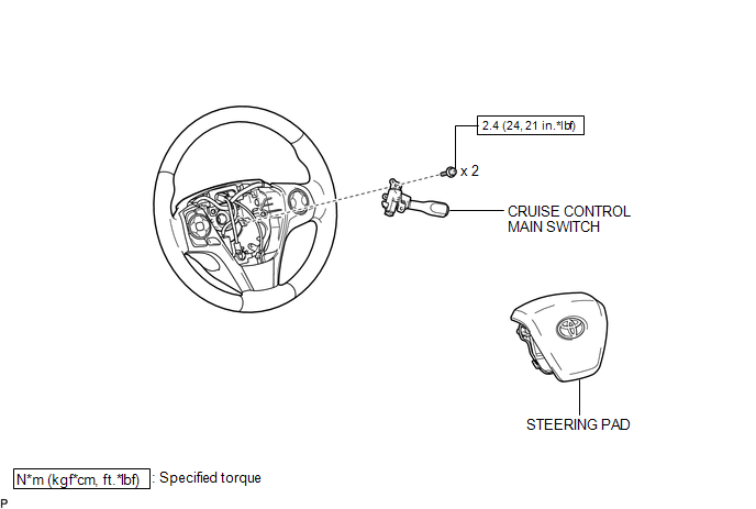
COMPONENTS
ILLUSTRATION
Removal
REMOVAL
PROCEDURE
1. REMOVE STEERING PAD
(See page .gif) )
)
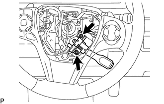
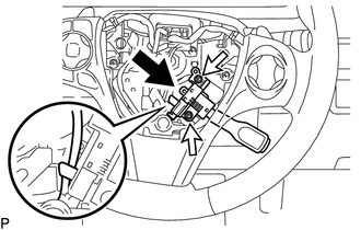
2. REMOVE CRUISE CONTROL MAIN SWITCH
|
(a) Remove the 2 screws. |
|
|
(b) Disconnect the connector and remove the cruise control main switch shown in the illustration. |
|
Inspection
INSPECTION
PROCEDURE
1. INSPECT CRUISE CONTROL MAIN SWITCH
(a) for vehicles without vehicle-to-vehicle distance control mode:
(1) Measure the resistance according to the value(s) in the table below.
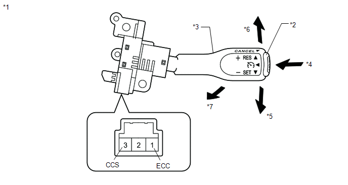 Text in Illustration
|
*1 |
Component without harness connected: (Cruise Control Main Switch) |
*2 |
Main Switch |
|
*3 |
Lever |
*4 |
ON/OFF |
|
*5 |
- SET |
*6 |
+ RES |
|
*7 |
CANCEL |
- |
- |
Standard Resistance:
|
Tester Connection |
Switch Condition |
Specified Condition |
|---|---|---|
|
1 (ECC) - 3 (CCS) |
Main Switch off*1 |
1 MΩ or higher |
|
Main Switch on |
Below 2.5 Ω |
|
|
+ RES |
235 to 245 Ω |
|
|
- SET |
617 to 643 Ω |
|
|
CANCEL |
1509 to 1571 Ω |
*1: Lever is in neutral position
If the result is not as specified, replace the cruise control main switch.
Installation
INSTALLATION
PROCEDURE
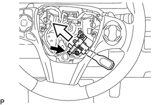
1. INSTALL CRUISE CONTROL MAIN SWITCH
(a) Connect the connector.
|
(b) Install the cruise control main switch with the 2 screws shown in the illustration. Torque: 2.4 N·m {24 kgf·cm, 21 in·lbf} |
|
2. INSTALL STEERING PAD
(See page .gif) )
)
 Cruise Control
...

Other materials about Toyota Venza:
Afs Ecu
Components
COMPONENTS
ILLUSTRATION
Installation
INSTALLATION
PROCEDURE
1. INSTALL AFS ECU
(a) Engage the guide.
(b) Install the AFS ECU with the bolt.
(c) Connect the connector.
2. INSTA ...
Steering Pad Switch Circuit
DESCRIPTION
This circuit sends an operation signal from the steering pad switch assembly
to the radio and display receiver assembly.
If there is an open in the circuit, the audio system cannot be operated using
the steering pad switch assembly.
If there ...
Installation
INSTALLATION
PROCEDURE
1. INSTALL TIMING CHAIN COVER SUB-ASSEMBLY
(a) Apply a light coat of engine oil to 2 new oil pump gaskets and new
oil hole cover gasket.
(b) Install the 2 new oil pump gas ...

0.1139