Toyota Venza: Crankshaft Position Sensor
Components
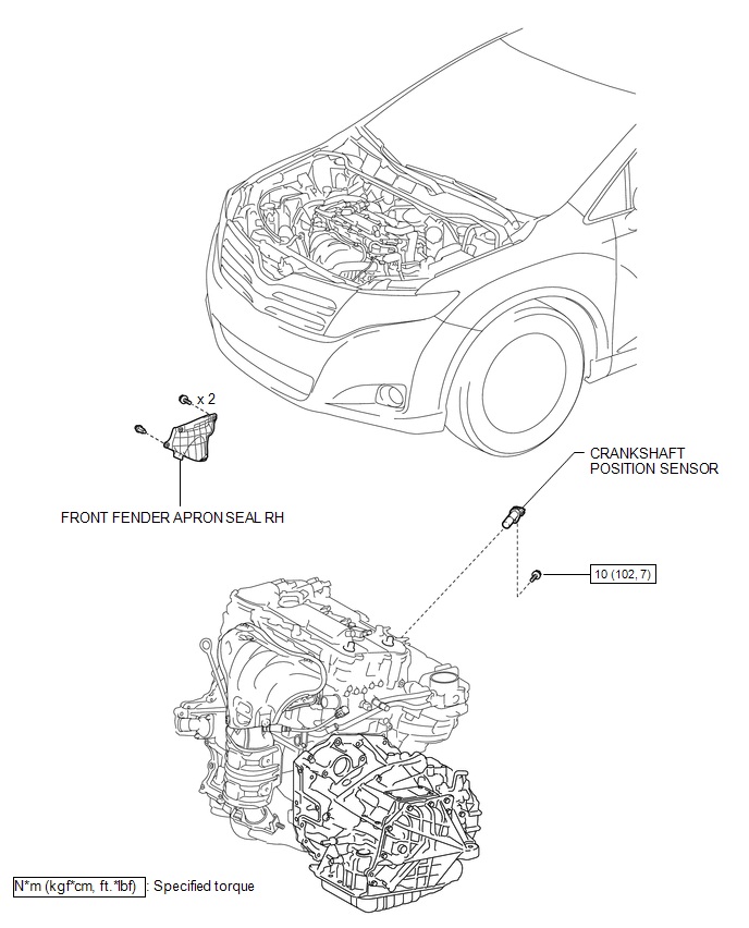
COMPONENTS
ILLUSTRATION
Removal
REMOVAL
PROCEDURE
1. REMOVE FRONT FENDER APRON SEAL RH
.gif)
2. REMOVE CRANKSHAFT POSITION SENSOR
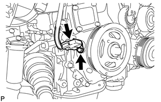
(a) Disconnect the sensor connector.
(b) Remove the bolt and sensor.
Inspection
INSPECTION
PROCEDURE
1. INSPECT CRANKSHAFT POSITION SENSOR
 Text in Illustration
|
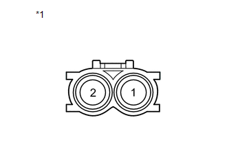
*1 |
Component without harness connected (Crank Position Sensor) |
(a) Measure the resistance according to the value(s) in the table below.
Standard Resistance:
|
Tester Connection |
Condition |
Specified Condition |
|---|---|---|
|
1 - 2 |
Cold |
1630 to 2740 Ω |
|
Hot |
2065 to 3225 Ω |
HINT:
In the table above, the terms "Cold" and "Hot" refer to the temperature of the coils. "Cold" means approximately -10 to 50°C (14 to 122°F). "Hot" means approximately 50 to 100°C (122 to 212°F).
If the result is not as specified, replace the crankshaft position sensor.
Installation
INSTALLATION
PROCEDURE
1. INSTALL CRANKSHAFT POSITION SENSOR
(a) Apply a light coat of engine oil to the O-ring of the crankshaft position sensor.
NOTICE:
If reusing the crankshaft position sensor, be sure to inspect the O-ring.
(b) Install the crankshaft position sensor to the timing chain cover sub-assembly with the bolt.
Torque:
10 N·m {102 kgf·cm, 7 ft·lbf}
NOTICE:
- If the crankshaft position sensor has been struck or dropped, replace it.
- Make sure that the O-ring is not cracked or moved out of place when installing the crankshaft position sensor.
(c) Connect the crankshaft position sensor connector.
2. INSPECT FOR OIL LEAK
3. INSTALL FRONT FENDER APRON SEAL RH
.gif)
 Camshaft Position Sensor
Components
COMPONENTS
ILLUSTRATION
Installation
INSTALLATION
PROCEDURE
1. INSTALL CAMSHAFT POSITION SENSOR (for Exhaust Side)
(a) Apply a light coat of engine oil to the O-ring of the cam ...
 Ecm
Ecm
...
Other materials about Toyota Venza:
Glossary of tire terminology
...
Installation
INSTALLATION
PROCEDURE
1. INSTALL HOOD LOCK CONTROL CABLE ASSEMBLY
(a) Pass the hood lock control cable assembly into the engine compartment.
(b) Pass the cable through the upper radiator support.
(c) Engage the each clamp shown in the illustration.
2. I ...
Short in Sensor with Motor Power Supply Circuit (B2658)
DESCRIPTION
This DTC is stored if sensor voltage does not reach the designated voltage while
the slide motor is operating.
DTC Code
DTC Detection Condition
Trouble Area
B2658
Malfunction in suppl ...

0.1432