Toyota Venza: Compressor Solenoid Circuit (B1451/51)
DESCRIPTION
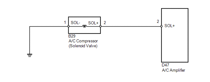
In this circuit, the A/C compressor receives a refrigerant compression demand signal from the A/C amplifier.
Based on this signal, the A/C compressor changes the amount of compressor output.
|
DTC No. |
DTC Detection Condition |
Trouble Area |
|---|---|---|
|
B1451/51 |
Open or short in A/C compressor solenoid circuit |
|
WIRING DIAGRAM
PROCEDURE
|
1. |
INSPECT A/C COMPRESSOR (SOLENOID VALVE) |
|
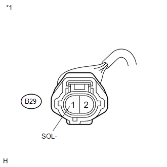
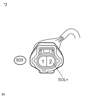
(a) Disconnect the A/C compressor (solenoid valve) connector. |
|
(b) Measure the resistance according to the value(s) in the table below.
Standard Resistance:
|
Tester Connection |
Condition |
Specified Condition |
|---|---|---|
|
B29-2 (SOL+) - B29-1 (SOL-) |
20°C (68°F) |
10 to 11 Ω |
|
Result |
Proceed to |
|---|---|
|
OK |
A |
|
NG (for 2GR-FE) |
B |
|
NG (for 1AR-FE) |
C |
|
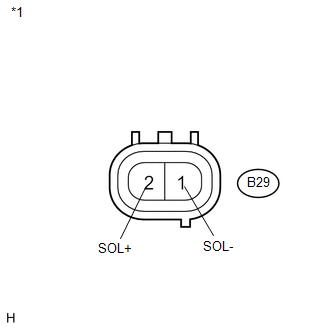
*1 |
Component without harness connected (A/C Compressor (Solenoid Valve)) |
| B | .gif) |
REPLACE A/C COMPRESSOR (SOLENOID VALVE) |
| C | |
REPLACE A/C COMPRESSOR (SOLENOID VALVE) |
|
.gif)
|
2. |
CHECK HARNESS AND CONNECTOR (A/C COMPRESSOR (SOLENOID VALVE) - BODY GROUND) |
|
(a) Measure the resistance according to the value(s) in the table below. Standard Resistance:
|
|
| NG | |
REPAIR OR REPLACE HARNESS OR CONNECTOR |
|
|
3. |
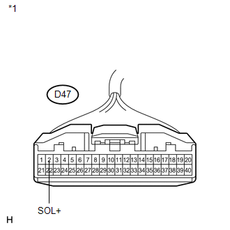
CHECK HARNESS AND CONNECTOR (A/C COMPRESSOR (SOLENOID VALVE) - A/C AMPLIFIER) |
|
(a) Disconnect the A/C amplifier connector. |
|
|
(b) Measure the resistance according to the value(s) in the table below. Standard Resistance:
Result:
|
|
| A | |
REPAIR OR REPLACE HARNESS OR CONNECTOR |
| B | |
PROCEED TO NEXT SUSPECTED AREA SHOWN IN PROBLEM SYMPTOMS TABLE |
| C | |
REPLACE A/C AMPLIFIER |
 Driver Side Solar Sensor Short Circuit (B14A2)
DESCRIPTION
The solar sensor is installed on the upper side of the instrument panel. It detects
sunlight to control air conditioning AUTO mode. The output voltage from the solar
sensor varies i ...
 BUS IC Communication Malfunction (B1497/97)
DESCRIPTION
The air conditioning harness connects the A/C amplifier and each servo. The A/C
amplifier supplies power and sends operation instructions to each servo through
the air conditioning ha ...
Other materials about Toyota Venza:
Oxygen (A/F) Sensor Pumping Current Circuit / Open (Bank 1 Sensor 1) (P2237-P2239,P2252,P2253)
DESCRIPTION
Refer to DTC P2195 (See page ).
HINT:
Although the DTC titles say oxygen sensor, these DTCs relate to the air fuel
ratio sensor.
DTC No.
DTC Detection Condition
Trouble Area
P2237
...
Diagnostic Trouble Code Chart
DIAGNOSTIC TROUBLE CODE CHART
HINT:
If a trouble code is stored during the DTC check, inspect the trouble areas listed
for that code. For details of the code, refer to the "See page" below.
Main Body
DTC Code
Detection Ite ...
On-vehicle Inspection
ON-VEHICLE INSPECTION
PROCEDURE
1. INSPECT BRAKE BOOSTER ASSEMBLY
(a) Airtightness check
(1) Start the engine and stop it after 1 or 2 minutes. Slowly depress
the brake pedal several times.
HINT:
If the pedal can be depressed to the ...

0.1245