Toyota Venza: Compressor Lock Sensor Circuit (B1422/22)
SYSTEM DESCRIPTION
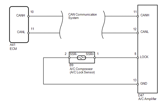
The ECM sends the engine speed signal to the A/C amplifier via CAN communication.
The A/C amplifier reads the difference between compressor speed and engine speed. When the difference becomes too large, the A/C amplifier determines that the compressor is locked, and turns the magnetic clutch off.
|
DTC No. |
DTC Detection Condition |
Trouble Area |
|---|---|---|
|
B1422/22 |
Open or short in compressor lock sensor circuit |
|
WIRING DIAGRAM
PROCEDURE
|
1. |
CHECK CAN COMMUNICATION SYSTEM |
(a) Use the Techstream to check if the CAN communication system is functioning normally.
|
Result |
Proceed to |
|---|---|
|
CAN DTC is not output |
A |
|
CAN DTC is output |
B |
| B | .gif) |
GO TO CAN COMMUNICATION SYSTEM |
|
.gif)
|
2. |
INSPECT A/C COMPRESSOR (A/C LOCK SENSOR) |
|
(a) Disconnect the A/C compressor connector. |
|
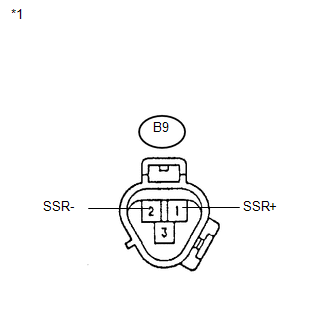
(b) Measure the resistance according to the value(s) in the table below.
Standard Resistance:
|
Tester Connection |
Condition |
Specified Condition |
|---|---|---|
|
B9-1 (SSR+) - B9-2 (SSR-) |
20°C (68°F) |
160 to 320 Ω |
|
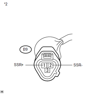
*1 |
Component without harness connected (A/C Compressor) |
| NG | |
REPLACE A/C COMPRESSOR (A/C LOCK SENSOR) |
|
|
3. |
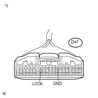
CHECK HARNESS AND CONNECTOR (A/C AMPLIFIER - A/C LOCK SENSOR) |
|
(a) Disconnect the A/C amplifier connector. |
|
|
(b) Measure the resistance according to the value(s) in the table below. Standard Resistance:
Result:
|
|
| A | |
REPAIR OR REPLACE HARNESS OR CONNECTOR |
| B | |
PROCEED TO NEXT SUSPECTED AREA SHOWN IN PROBLEM SYMPTOMS TABLE |
| C | |
REPLACE A/C AMPLIFIER |
 Evaporator Temperature Sensor Circuit (B1413/13)
DESCRIPTION
The evaporator temperature sensor is installed on the evaporator in the air conditioning
unit to detect the cooled air temperature that has passed through the evaporator
and to contro ...
 Room Temperature Sensor Circuit (B1411/11)
DESCRIPTION
The room temperature sensor is installed in the instrument panel. It detects
the cabin temperature to control the air conditioning AUTO mode. The resistance
of the room temperature se ...
Other materials about Toyota Venza:
Dtc Check / Clear
DTC CHECK / CLEAR
1. CHECK DTC (CHECK USING TECHSTREAM)
(a) Connect the Techstream to the DLC3.
(b) Turn the ignition switch to ON.
(c) Turn the Techstream on.
(d) Enter the following menus: Body Electrical / Navigation System / Trouble
Codes.
(e) Chec ...
Fuel Tank Cap
Inspection
INSPECTION
PROCEDURE
1. INSPECT FUEL TANK CAP ASSEMBLY
(a) Visually check that the fuel tank cap assembly and gasket are not
deformed or damaged.
Text in Illustration
*a
Gasket
...
Removal
REMOVAL
PROCEDURE
1. REMOVE BRAKE BOOSTER ASSEMBLY
HINT:
Refer to the instructions for Removal of the brake booster assembly (See page
).
2. REMOVE HEADLIGHT LEVELING ECU ASSEMBLY (w/ HID Headlight System)
3. REMOVE STOP LIGHT SWITCH ASSEMBLY
4. ...

0.1453