Toyota Venza: Components
COMPONENTS
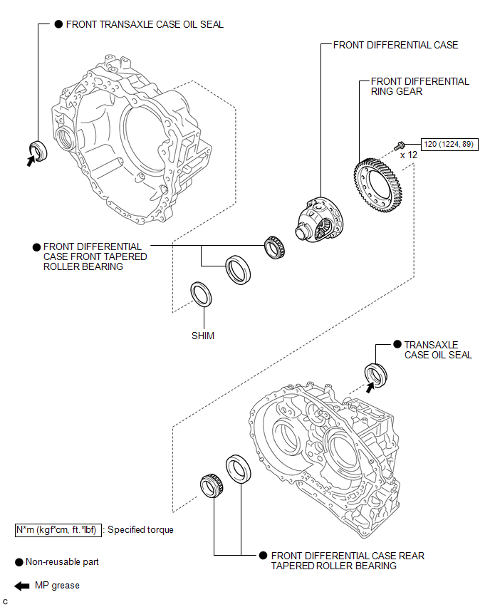
ILLUSTRATION
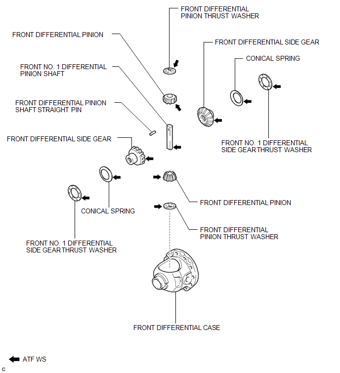
ILLUSTRATION

 Disassembly
DISASSEMBLY
PROCEDURE
1. REMOVE FRONT TRANSAXLE CASE OIL SEAL
(a) Using SST, remove the front transaxle case oil seal from the transaxle
housing.
SST: 09308-00010
...
Other materials about Toyota Venza:
Terminals Of Ecu
TERMINALS OF ECU
1. CHECK MAIN BODY ECU (DRIVER SIDE JUNCTION BLOCK ASSEMBLY)
(a) Disconnect the main body ECU (driver side junction block assembly) connectors.
(b) Measure the resistance and voltage according to the value(s) in the table
below.
...
System Description
SYSTEM DESCRIPTION
1. GENERAL
The windshield deicer system's thin heater wires are attached to the inside of
the front window and deice the window surface quickly. The indicator light illuminates
while the system is operating. The system automaticall ...
ECU Power Source Circuit
DESCRIPTION
When the ignition switch is turned to ON, voltage from the ECM's MREL terminal
is applied to the EFI MAIN relay. This causes the contacts of the EFI MAIN relay
to close, which supplies power to terminal +B of the TCM.
WIRING DIAGRAM
PR ...

0.1166