Toyota Venza: Components
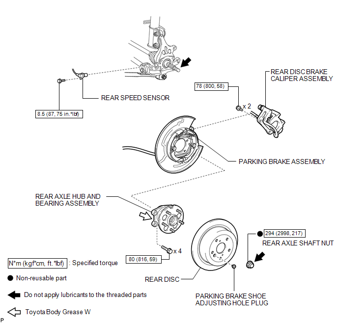
COMPONENTS
ILLUSTRATION

 On-vehicle Inspection
ON-VEHICLE INSPECTION
CAUTION / NOTICE / HINT
HINT:
Use the same procedure for the RH side and LH side.
The procedure listed below is for the LH side.
PROCEDURE
1. REMOVE REAR W ...
Other materials about Toyota Venza:
Calculation formula for your vehicle
1. Cargo capacity
2. Total load capacity (vehicle capacity weight)
When 2 people with the combined weight of A lb. (kg) are riding in your vehicle,
which has a total load capacity (vehicle capacity weight) of B lb. (kg), the available
amount of cargo a ...
Security Indicator Light Circuit
DESCRIPTION
The security indicator light blinks continuously due to a continuous signal received
from the transponder key ECU assembly while in the armed state.
WIRING DIAGRAM
CAUTION / NOTICE / HINT
NOTICE:
If the transponder key ECU assembly is repl ...
Installation
INSTALLATION
PROCEDURE
1. CLEAN QUARTER WINDOW ASSEMBLY
(a) Clean the outer edges of the quarter window assembly with a non-residue
solvent.
NOTICE:
Do not touch the glass surface after cleaning it.
Be careful not to ...

0.1218