Toyota Venza: Components
COMPONENTS
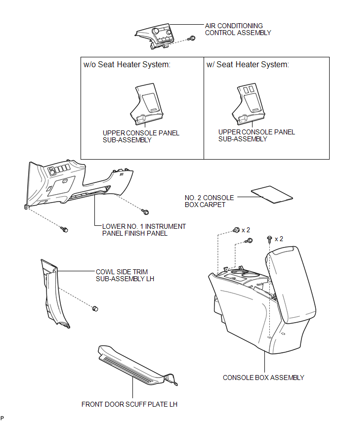
ILLUSTRATION
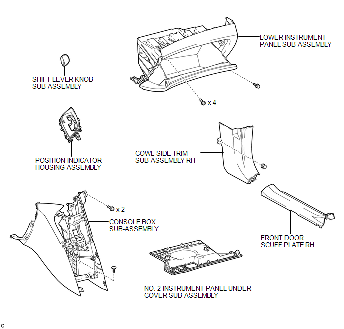
ILLUSTRATION
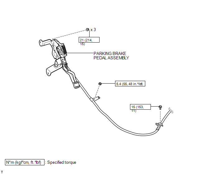
ILLUSTRATION
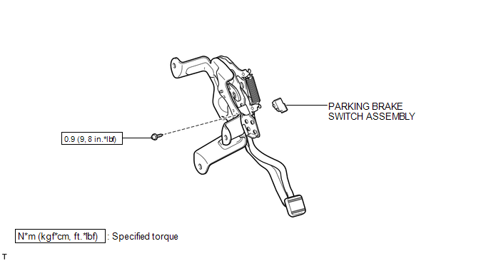
ILLUSTRATION

 Removal
REMOVAL
PROCEDURE
1. DISCONNECT CABLE FROM NEGATIVE BATTERY TERMINAL
CAUTION:
Wait at least 90 seconds after disconnecting the cable from the negative (-)
battery terminal to disable the SRS sys ...
Other materials about Toyota Venza:
Installation
INSTALLATION
CAUTION / NOTICE / HINT
NOTICE:
When disconnecting the steering intermediate shaft assembly and pinion shaft
of steering gear assembly, be sure to place matchmarks before servicing.
PROCEDURE
1. INSTALL TIE ROD ASSEMBLY LH
(a) I ...
Clock Display Circuit
DESCRIPTION
The accessory meter assembly uses this circuit to communicate with the combination
meter assembly via the direct line. The accessory meter assembly uses this circuit
to receive the drive monitor switch signals from the combination meter assemb ...
Fuel Pump Control Circuit
DESCRIPTION
1. w/o Smart Key System
When the engine is cranked, the starter relay drive signal output from the ignition
switch is input into the STA terminal of the ECM, and the NE signal generated by
the crankshaft position sensor is also input into the ...

0.1416